Robert Brown Focuser Controller build, step by step #11

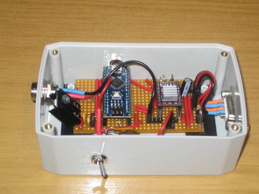
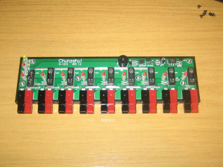
Finished the lid. No photos yet, but I’ve run some of the tests. The LEDs and pushbuttons appear to work fine, though the buzzer doesn’t. I wasn’t entirely happy about my connector for the buzzer though, so I may need to remake that.

Next I need to connect 12V power and rig up the motors to test them. There’s a bit more work involved there though as I’ve decided to move away from using 5.5/2.1mm power connector plugs and switch to two pin GX12 connectors. I don’t have anything with a GX12 plug on at my desk though, so I shall see if I have enough bits to make an inline 5.5/2.1mm socket to GX12 converter in which case I can just power it from a standard 12V wall-wart.

Then I need to find some suitable four-way cable to connect up the motors. I’d forgotten about this, I have to admit. I suspect cat5e might actually be sufficient. I think it should be good for an amp per conductor and the motors aren’t rated that high if I recall correctly. The only problem is that it’s so awkward to work with for soldering.

Posted in Astro Equipment, Astronomy | Tagged , | Leave a comment

Robert Brown Focuser Controller build, step by step #10

Mostly done and in a box now. Just need to finish making up the lid with the buttons and LEDs on.

Posted in Astro Equipment, Astronomy | Tagged , | Leave a comment

Robert Brown Focuser Controller build, step by step #9

I’ve just realised that I forgot to put in the current-limiting resistor for the buzzer (that’s what I assume it’s there for, anyhow). Probably because it doesn’t appear on the stripboard layouts which aren’t always kept up to date with the most recent changes to the design. I assume it was added later. Fortunately there’s room to move the pin header for connecting the buzzer further away from the Nano and I can just drop a resistor in across a break in the track.

Posted in Astro Equipment, Astronomy | Tagged , | Leave a comment

Robert Brown Focuser Controller build, step by step #8

This morning I grabbed a scribing tool from the workshop and ran it down all the “blank” sections of the stripboard on the first board a few times to try to clear out any tiny drops of solder that might have been bridging tracks. I also found one place where my soldering might have unintentionally bridged two tracks though I couldn’t tell for certain. If there was a bridge then it would have pulled the RESET (pin 3) input to ground. As that input is active low I imagine it could well have caused the behaviour I was seeing. I removed the solder using some braid, cleaned between the tracks and remade the join just to be sure. I now have a Nano sitting in the socket and behaving as I would expect 🙂

Now as if it’s not enough having to deal with my eyesight not being what it was in my youth, I can’t remember where I put my stepper drivers either 😀

Posted in Astro Equipment, Astronomy | Tagged , | Leave a comment

Darkstar restoration, part 4

Having found a 65mm hole saw, I screwed a block of scrap timber to the inside of the OTA using the existing mounting holes having marked the centre as best I could.

and cut a larger diameter hole for the new focuser.

I didn’t quite get it perfectly centred on the old hole, but that shouldn’t make any difference.

Posted in Astro Equipment, Astronomy | Tagged , | 2 Comments

Mount power distribution box

A while back I picked up a 12V power distribution box second-hand with a view to putting it on top of one of my mounts to provide 12V power to all the attached bits and pieces whilst only requiring a single supply cable from the pier:

I thought I’d open it up just to see what was inside, which turned out to be not very much at all…

And then I realised that the instructions even give a rough circuit diagram.

The connectors look very good. I might have to pinch a few ideas from this in the future.

Posted in Astro Equipment, Astronomy | Leave a comment

Robert Brown Focuser Controller build, step by step #7

I think it must be a short somewhere between some of the tracks. This evening I’ve built a new board from the ground up, plugged in the same Nano and stepper driver and it’s running “blink” fine. A small part of the layout is slightly different from the first one as I realised I could do it a little more neatly, but the circuit is clearly the same. I guess I just need to get the big magnifying glass out so I can check things over better.

At least I have something I can continue working with now.

Posted in Astro Equipment, Astronomy, Projects | Tagged , | Leave a comment

Robert Brown Focuser Controller build, step by step #6

Having finished the circuit board I plugged in the Nano and motor controller and connected it to a USB port (without any other power source connected). The power LED lit on the Nano, but nothing else happened and I wasn’t able to connect to upload a sketch. Unplugging the Nano from the board allows it to work exactly as expected. I can upload the “blink” sketch and it runs ok. Plug the Nano back in and the sketch doesn’t start and there’s no response when attempting to upload.

I can’t find any obvious problems with the circuit or my soldering so far, but I have to assume that either the 12V supply is required in some way that isn’t obvious to me or that there must be some issue with my soldering that I just can’t see.

As stealing the eyes of a teenager tends to be frowned upon I’m thinking my best option at this point may be to build a second board and test the Nano out at each stage to see what happens. The only other thing I can think of for the time being is to connect up the 12V supply and check if any magic smoke comes out, but I’m not so keen on that approach whilst there are still other things to try. I could perhaps attempt to build the circuit on a breadboard, but I’m not convinced there’d be room.

Posted in Astro Equipment, Astronomy, Projects | Tagged , | Leave a comment

Robert Brown Focuser Controller build, step by step #5

I now have almost all the components in place.

The large diode at the top left wasn’t in the original plan I worked from. That’s the reverse voltage protection diode. Obviously no-one, least of all me, is ever going to connect the power the wrong way around anyhow, are they? The leads on this diode were larger than the hole diameter, so I ended up buying some small diameter drills from Amazon and enlarging two of the holes to about 1.5mm so it would fit.

The top right I had to reorganise a little. Fitted around the top of the header for the Nano is the diode that protects the voltage regulator. The two resistors and the third diode form the voltage sensing circuit that means the Nano won’t try to drive the motors unless 12V power is connected. To make that all work I had to move one of the capacitors for the voltage regulator and make another cut in the track feeding the Vin pin on the Nano (which is bridged by the diode).

All that remains now is the voltage regulator itself, which will fit at the top on the very right hand edge.

As I’m not using some of the other features of the focuser controller such as the temperature sensor and the OLED display, there’s quite a bit of space free in the middle of the board. When I make the next one I might move the Nano to the left two or three columns to make a bit more space on the right hand side for the additional components at the top right.

Posted in Astro Equipment, Astronomy, Projects | Tagged , | Leave a comment

Robert Brown Focuser Controller build, step by step #4

In the end I couldn’t find a single application that would do what I wanted, so I just decided to start cutting tracks and see where I ended up 🙂

And then spent a happy hour or two soldering in all the headers,

Finally adding all the string to join the various bits of track together.

Oh, I put the two capacitors in for the voltage regulator too.

Next is a bit of testing to make sure I don’t have any bridged tracks where I don’t want them. There is actually one place where I deliberately bridged the tracks with a lump of solder. The DRV8825 “sleep” and “reset” pins are next to each other and both clamped to the 5V output of the Nano, so I just dragged a lump of solder across the tracks they use.

Once I’ve checked the soldering over there’s not a lot left to do — the resistor network for the pushbuttons, current-limiting resistor for the buzzer, two resistors and a diode for the supply voltage sensing, another couple of diodes, a capacitor and the voltage regulator and I think I’m done. I may need to break a few more tracks to fit all of those in, but that’s not a problem.

Posted in Astro Equipment, Astronomy, Projects | Tagged , | Leave a comment