
I now have almost all the components in place.
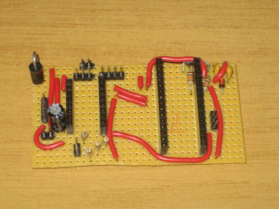
The large diode at the top left wasn’t in the original plan I worked from. That’s the reverse voltage protection diode. Obviously no-one, least of all me, is ever going to connect the power the wrong way around anyhow, are they? The leads on this diode were larger than the hole diameter, so I ended up buying some small diameter drills from Amazon and enlarging two of the holes to about 1.5mm so it would fit.
The top right I had to reorganise a little. Fitted around the top of the header for the Nano is the diode that protects the voltage regulator. The two resistors and the third diode form the voltage sensing circuit that means the Nano won’t try to drive the motors unless 12V power is connected. To make that all work I had to move one of the capacitors for the voltage regulator and make another cut in the track feeding the Vin pin on the Nano (which is bridged by the diode).
All that remains now is the voltage regulator itself, which will fit at the top on the very right hand edge.
As I’m not using some of the other features of the focuser controller such as the temperature sensor and the OLED display, there’s quite a bit of space free in the middle of the board. When I make the next one I might move the Nano to the left two or three columns to make a bit more space on the right hand side for the additional components at the top right.