
No, not an Australian one 🙂
I’m aware these can happen due to (I think) ice crystals floating in the sky, but it’s the first time I’ve seen one.

No, not an Australian one 🙂
I’m aware these can happen due to (I think) ice crystals floating in the sky, but it’s the first time I’ve seen one.
Another Swimfit session today:
6 x 1 length backstroke, 1 length breaststroke, 1 length front crawl, easy pace.
One minute rest
6 x 1 length front crawl, average pace, 20 seconds rest
20 lengths quick front crawl
Rest until breathing returns to normal
4 x 1 length breaststroke kick, 15 seconds rest
8 x 1 length breaststroke pull, 15 seconds rest
4 x 2 lengths breaststroke, 30 seconds rest
1 length front crawl, 2 lengths breaststroke, 2 lengths backstroke, 1 length front crawl, 30 seconds rest every two lengths
4 lengths front crawl easy pace
After that I made the distance up to 2km doing reps of 2 lengths front crawl with a tumble turn at the deep end.
I found this a very tough session. I don’t particularly struggle with backstroke though I know I could do with more body rotation and my pull isn’t really that great, but I find it exhausting to swim so the first set (the warm-up!) became quite hard towards the end. Breaststroke I also find very demanding.
On the plus side, I think my breaststroke is improving thanks to the pull and kick sets. (In fact I did the pull sets with a small dolphin kick just to keep the momentum up, otherwise my legs sink.) I made more effort to shoot my hands forward at speed during the arm recovery and realised I was exhaling explosively during the in-scull. Getting the breathing more controlled really helped. What my legs are doing in the kick is still something of a mystery, but I’m trying to get my heels up to my bum, knees about hip-width apart and then kicking backwards rather than outwards. And to get legs and feet nicely streamlined at full extension.
No swimming tomorrow as I’m out on the “Swimming Coach” training course all day, but for the rest of the week the course starts at 1pm so I’ll try to get some pool time in first.
Total distance this month: 29,700m
Total distance this year: 29,700m
If it ever will be 🙁 So you really shouldn’t design systems that assume it is.
A couple of examples…
The bank I use for my business recently “improved security” for setting up transactions over the internet so that any new payees or changes in payment amounts and references (and a few other account details changes too) require a confirmation code to be entered. The confirmation code is sent to your phone as a text message. But mobile network coverage from our home and my office is so poor that I don’t get text messages, meaning I can no longer make payments using internet banking. I have to phone them up to set up the payments instead which takes considerably longer and means I can’t cut’n’paste details from emails or electronic invoices.
And today we were visited by a chap from the AA who is working for Volkswagen, updating the EMU firmware for their cars, presumably as a result of the emission-fixing scandal. He got out of his van holding his phone, saying “I can’t get any network coverage”.
“No”, I replied, “you won’t.”
“Oh. We’ll I can’t do the software update without mobile phone access.”
Fortunately he managed to do it a different way once I’d allowed his phone to connect to our wifi network, but that was only possible because I have a wifi network deliberately set up to provide access outdoors.
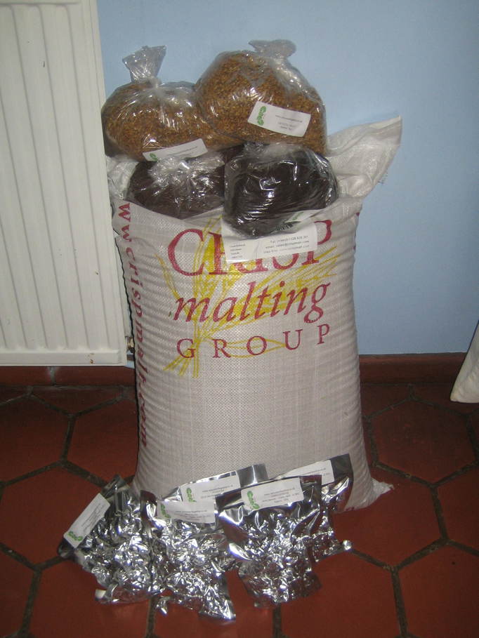
Can’t really blame him, to be honest. It’s very decent of him to carry this little lot all the way from the drive to the front door…
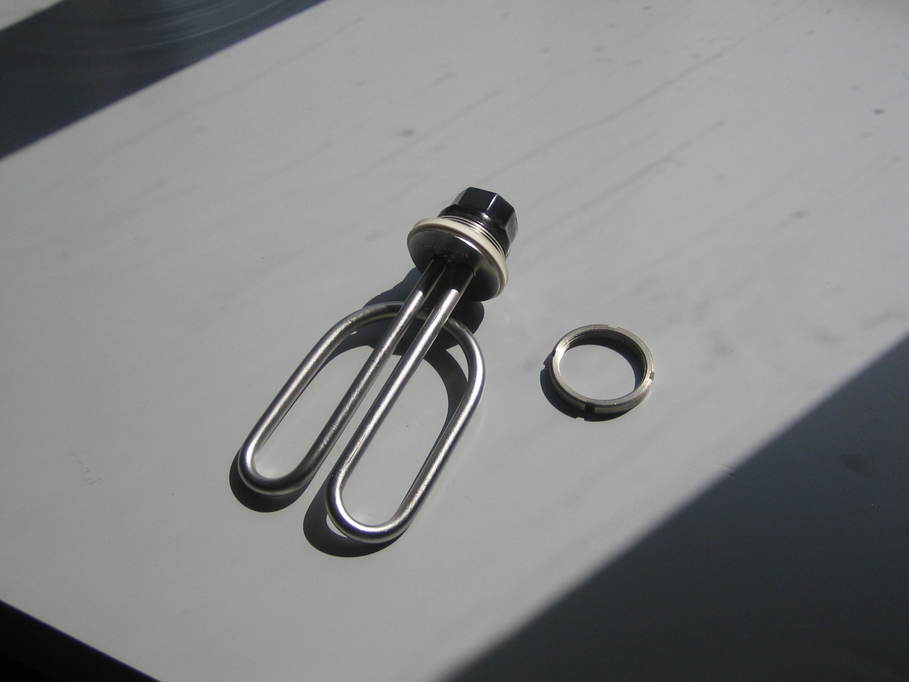
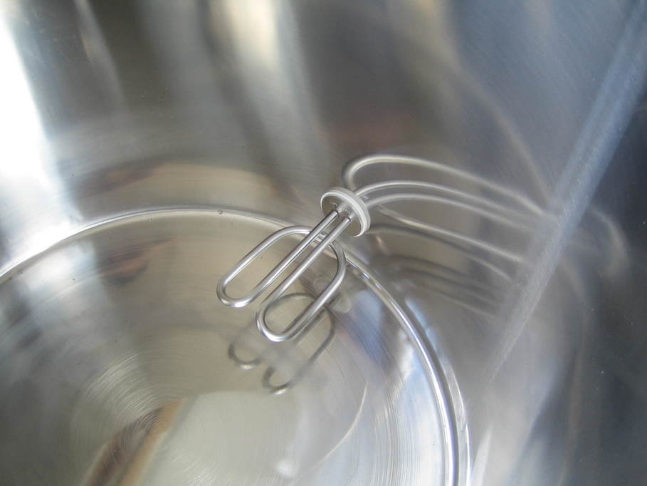
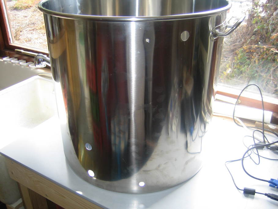
Starting with the easier one first. The first part of the plan was to fit a 2.4kW heating element:
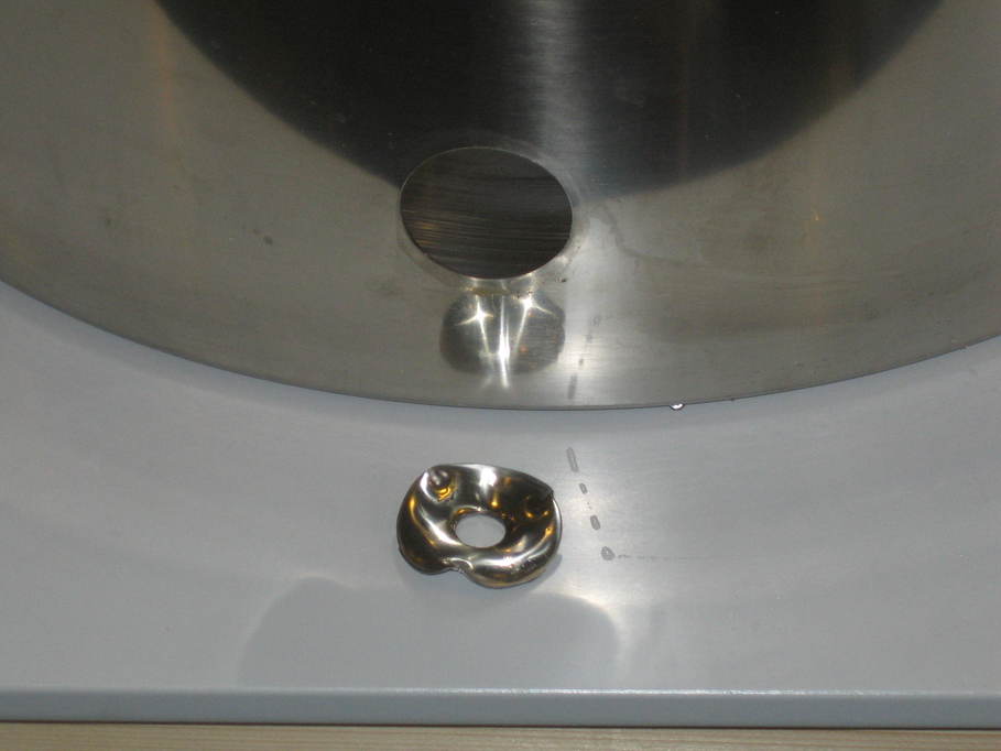
It needs a big hole, obviously and stainless isn’t the easiest of stuff to work with, so I used a Q-Max cutter of the appropriate size:
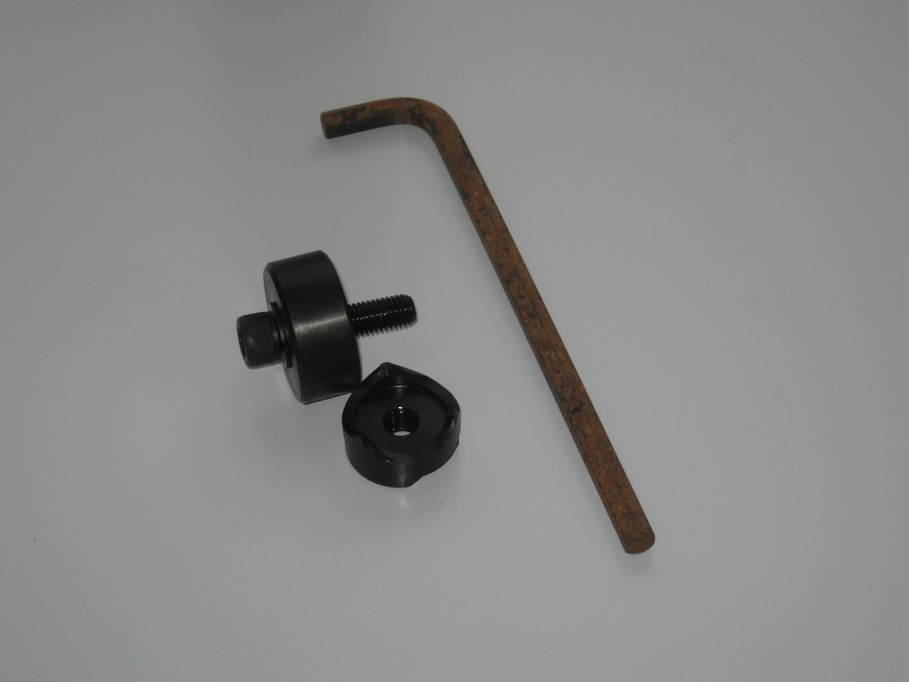
A pilot hole is still required, so to help in keeping the drill bit in place I put a few layers of masking tape on the metal.
The cutter works by pulling the cutting bit through the metal into a socket on the opposite side using a bolt passing through the pilot hole. Once the bolt is engaged, it’s just gradually tightened up using an Allen key:
It pierces the metal several times and gradually enlarges the cut, eventually pulling all the way through leaving an oddly-shaped waste piece and a beautifully clean cut:
That done it was just a case of fitting the element.
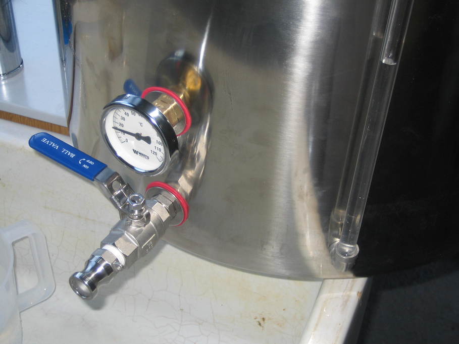
The holes for the other fittings were also made in the same way. I had a thermometer housing:
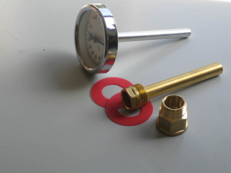
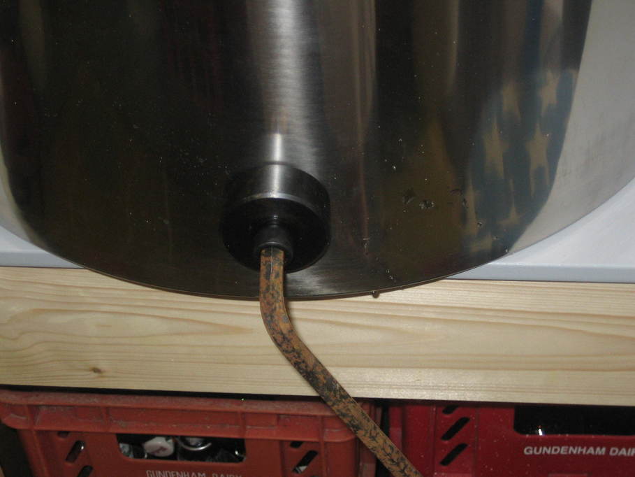
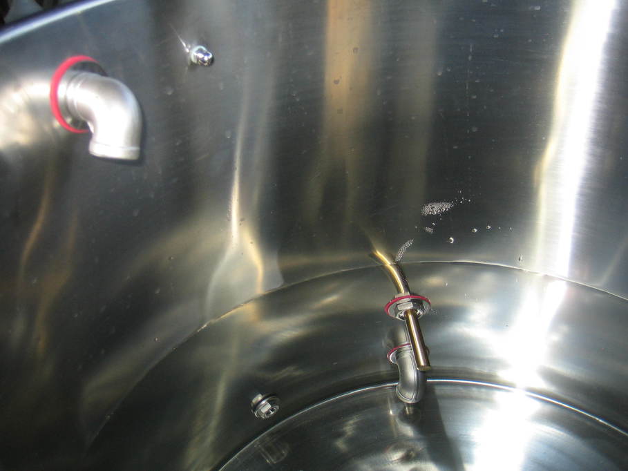
The tap (with an elbow on the inside so the tap actually draws from very close to the bottom of the pot):
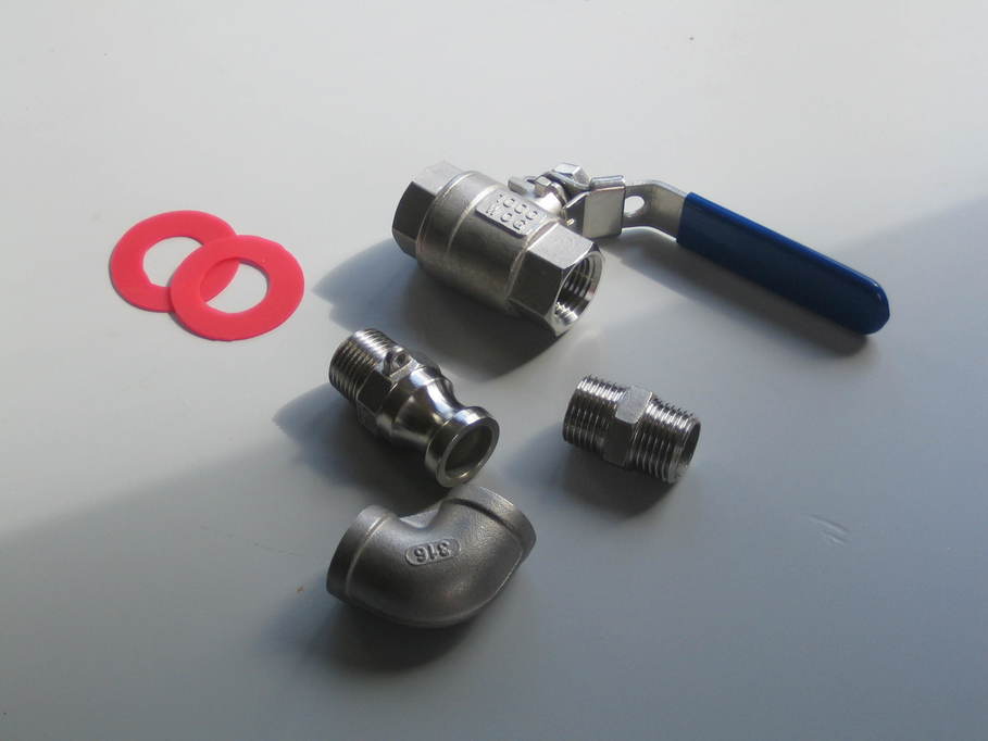
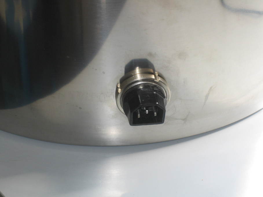
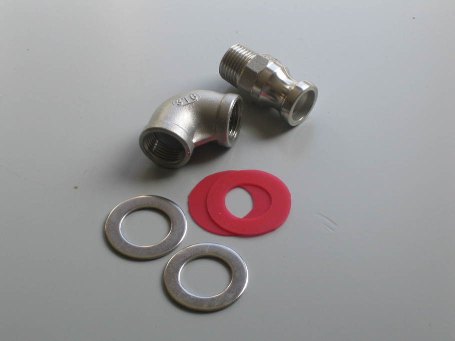
The water inlet:
And the sight tube:
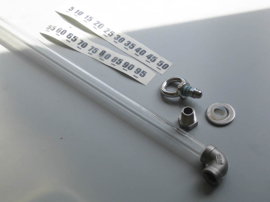
(The red seals for the fittings were cut from a silicone baking sheet, using a compass cutter sold by craft shops for cutting discs from cardboard and paper.)
It took a little while, but eventually I had all the holes cut.
That was all the hard work over, really. From there it was just a case of fitting the parts and nipping up the threads.
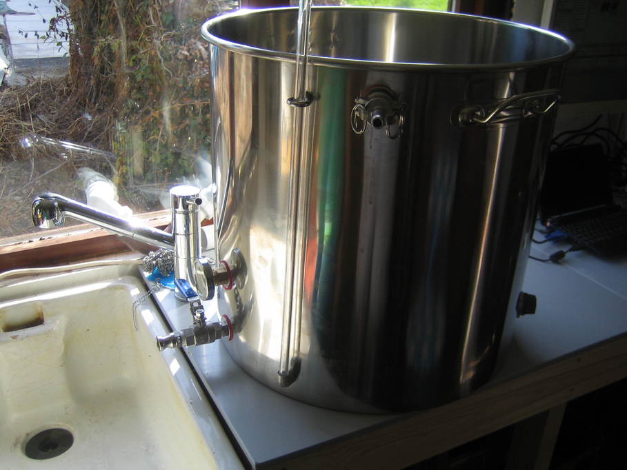
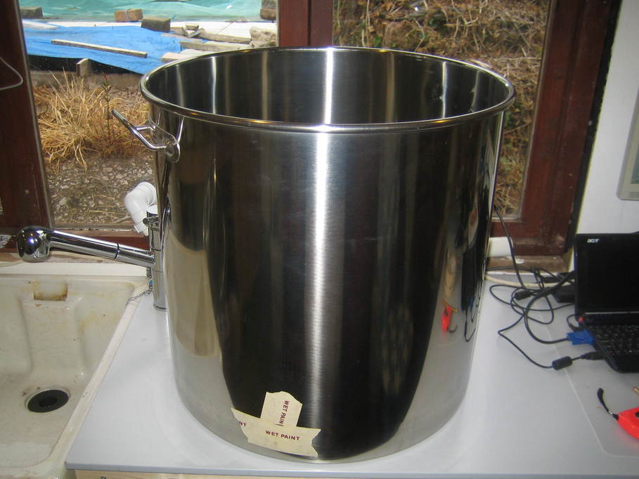
That done I poured in water so it was above all of the holes to check for leaks:
The boiler conversion was in fact pretty much the same. There’s no upper inlet or thermometer and there are two heater elements, but really that’s the only thing that is different.
“Counselor to the President”, whatever that means, but described by the BBC today as a “Top Trump aide”. Does that mean she can remember the stats on all the cards and knows which one is best?
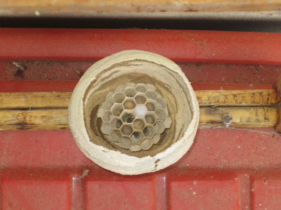
I had some empty hives stacked up in the apiary and when I was working there one day noticed a hornet flying about. It disappeared inside one of the empty hives where it had been knocked aside slightly (probably by a visiting deer or something like that).
When it left I opened up the boxes and removed the nest it had built, closing everything up again properly. The nest was in its very early stages, just holding the first batch of grubs the queen had laid.
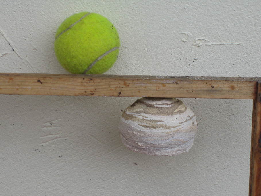
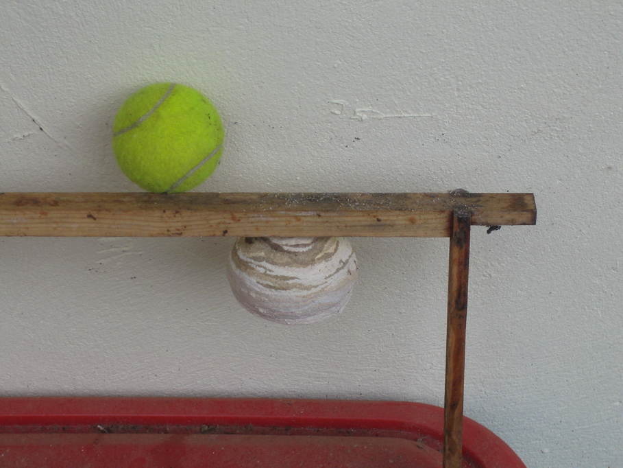
To give an idea of scale, here it is with a tennis ball.
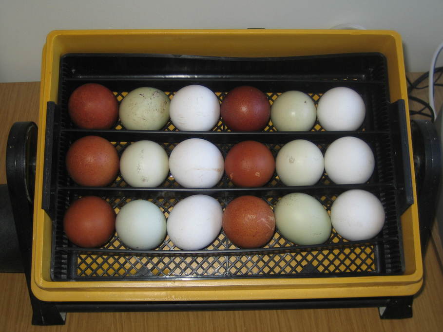
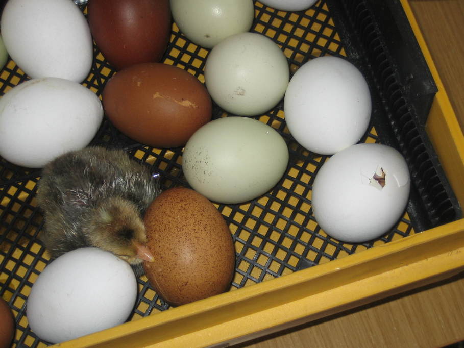
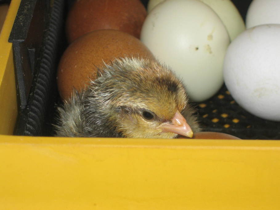
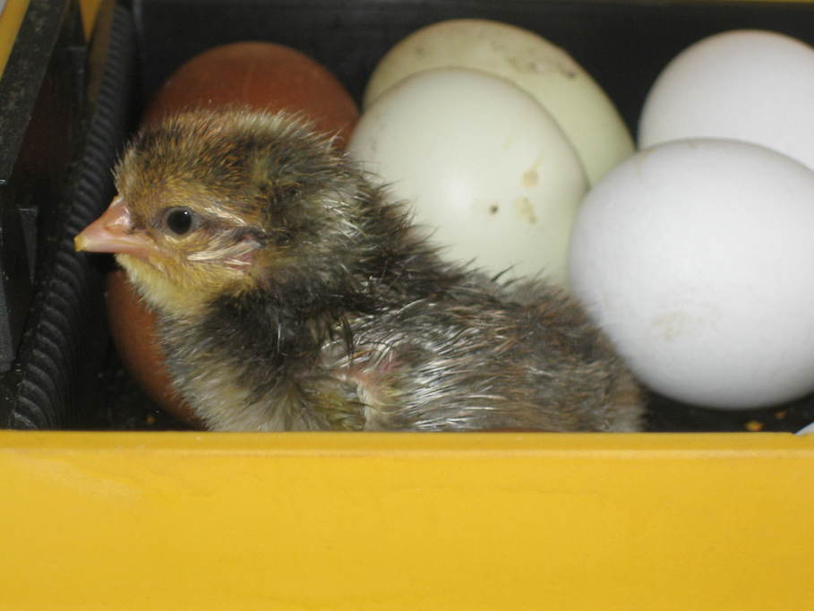
Most years I put some chicken eggs into an incubator to add to our flock that provide us with eggs and meat. This year I might try to set up a “chick cam” (somehow I feel that’s not going to get the desired results in a Google search) to watch the entire process (the first 20 days might be pretty boring though). Here are a few photos of the previous batch.
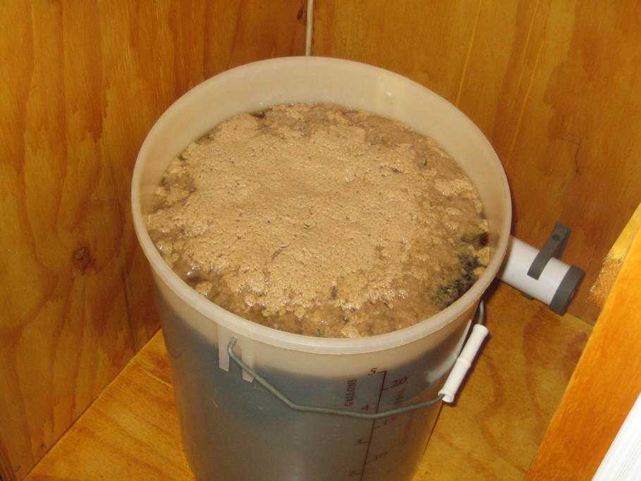
Just a quick photo of the first batch of beer made in the beer shack fermenting away nicely in my fermentation cabinet despite the cold temperatures outside.
Whilst clearing out the barn to allow space for the scaffolding, I came across the remains of this mangle, hidden away behind some other stuff that must have been there years:
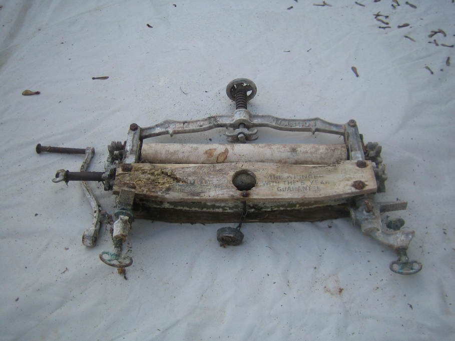
I wonder if they provided mangling services to Wile E. Coyote?
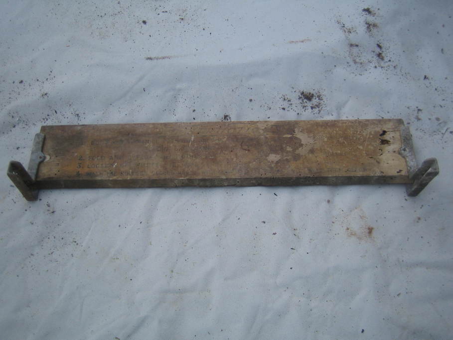
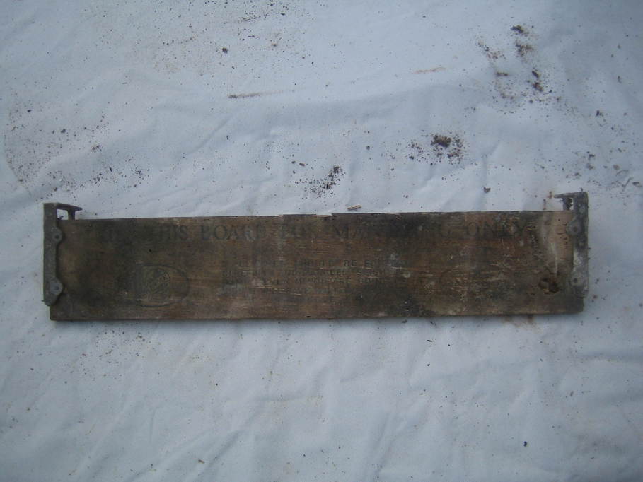
Also present was a bit that looks as though it needs attaching somehow, with wording stencilled on both sides:
A hunt for similar items in somewhat better order turned up this image from the Grace’s Guide website:
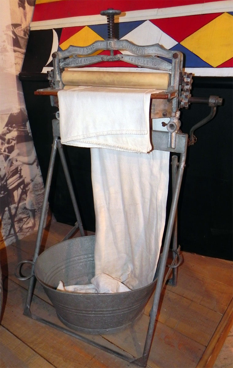
Clearly the one I found is missing the two tensioning bars for the top roller. I’ll have to hunt around to see if I can find them, though possibly it has been moved so many times that they have been lost.