My second right-angle finder based on a binocular objective is now built (if not yet cosmetically finished) and this time I’ve taken photos so I can now document the construction process.
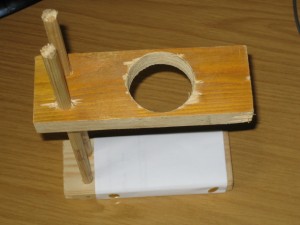
My aim was to make a functioning right-angle finder pretty much as cheaply as possible using whatever I had lying about. To that ends I started with one lens and its housing from a broken pair of binoculars. This doesn’t actually get assembled until the end, but there’s one thing it must be used for first: working out the focal length to enable the size of the rest of the pieces to be calculated. From a few scraps of wood I built this little stand:
The idea is to rest the lens housing in the hole and the top and adjust that block of wood up or down until an image is focused on the paper at the bottom (or it can be used sideways on). It’s possible to measure off the focal length directly if the image is focused at “infinity”, but I decided it would be easier to get something nearby in focus and use the formula 1/f = 1/a + 1/b, where f is the focal length, a is the distance from the lens to an object and b is the distance from the lens to the focused image. The filament in an incandescent light bulb seemed like a good choice, so I set up on the floor underneath one and brought the filament into focus. I measured the distance from the lens to the filament at 1800mm and lens to image at 200mm, giving a focal length of 180mm. As a check I repeated the test on another object and obtained the same result. I intend to use a Skywatcher kit 25mm eyepiece with this finder, so that would give 7.2x magnification which seems fine to me. If I want a little more magnification I can always drop down a few millimetres on the eyepiece focal length.
The length of the objective housing I measured at 58mm. A bit of research suggested that all mirror-based 1.25″ diagonals have an optical path length of 75mm. The focal plane of the 25mm eyepiece appears to be at about the same place as the chrome barrel starts and so I wanted the focal plane of the finder to be at the top of the diagonal, leaving me 47mm of optical path (180 – 58 – 75) to make up. I decided to knock 4mm off that to give a bit of play in case I’d not measured something correctly, giving a final length of 43mm.
Rummaging around the workshop I came up with a number of sections of upvc piping in various diameters. The smallest was 32.5mm inside diameter and 36.5mm outside diameter. It fitted very snugly over the barrel of the 25mm eyepiece, but was a little slack on my cheap £4.50 diagonal. Close enough though. I cut a 25mm length of this to match the length of the barrel on the diagonal. Next was a piece 37mm internal diameter, 41mm external. That was a neat fit over the first piece and an exceptionally tight fit over the threads on the objective housing. I tested I could make it fit by putting the end of the pipe in boiling water and then inserting the housing, which went in easily and the pipe shrank to fit. I cut a section of this to my required length of 43mm. I think the first may have been 32mm nominal solvent-weld waste water pipe, and the second 40mm nominal push-fit waste water pipe.
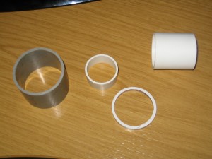
I cut the same length from a pipe of 49mm internal diameter to use as the mounting ring. I think this was left-over ducting supplied by BT for running phone lines. Finally I found one more piece that was pretty much an interference fit inside the 49mm pipe and about 1mm larger internal diameter than my second piece. Glued in place with araldite this would do the same job as the O-ring in the normal Skywatcher finders. An O-ring might have worked better for me, too, but I didn’t have any of the right size. Here are all the pieces:
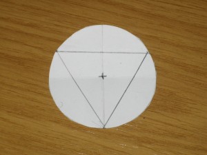
I glued the first section of pipe inside one end of the second to make the body of the finder and once that was dry set to marking and drilling out all the holes for the fittings and adjustment screws. I put a single hole in the body to hold a screw to lock the diagonal in place and tapped it out to 4mm. The (grey) adjustment ring needed much more work. I wanted three equally-spaced adjustment screws and two holes for the screws to fix the ring to the foot. As there was no way to reach those screws inside the adjustment ring, I also had to make two holes for screwdriver access in the top. I started by making a template to mark the positions of all the holes:
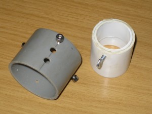
It’s actually quite easy to inscribe an equilateral triangle inside the circle. Start by folding the paper in half. Then open it out and fold in half at right angles to the first fold, so the ends of the first fold meet. Open it out again, and fold one edge up so the end of one of the existing folds meets the centre. The triangle is then the end-points of the last fold and the end of the diagonal opposite it. I used this to mark the positions of all the screws and drilled and tapped them out:
The locking screw for the diagonal is a stainless steel M4 12mm thumbscrew and the adjustment screws are M4 12mm allen bolts, also stainless. I actually decided in the end that I wasn’t happy with this adjustment ring (I was having a few niggles with the pillar drill at the time) and made a second to replace it later.
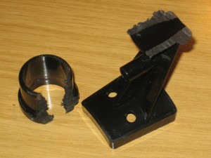
The foot for the finder is actually the mount from an old 8×20 finder with most of the ring sawn off:
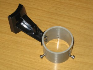
I cleaned this up, drilled two more pilot holes to match those in the adjustment ring and screwed them together with a couple of 2.5mm self-tapping screws:
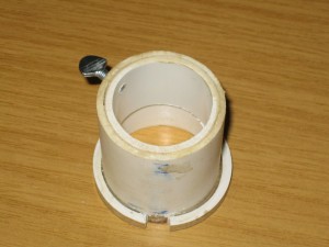
Finally I glued my O-ring substitute to the end of the diagonal body that would take the objective housing and when it was dry, removed a small piece to allow it to pass over the screws inside the adjustment ring:
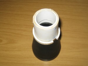
Assembly was then just a case of shrink-fitting the objective:
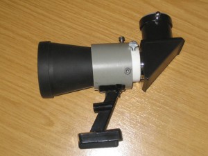
and then sliding the body through the adjustment rings and fitting the diagonal at the other end:
First tests suggest I should have no problem reaching focus by sliding the diagonal in and out a little before locking it in place.
The only jobs remaining are to clean it up a little and give it a splash of paint. I may also use some fuse wire to add cross-hairs to the eyepiece, but it does need to be very fine wire.

Pingback: My 10″ Dobsonian ‘build’ | www.tanstaafl.co.uk