Right then… Components… I’ve given links to the places I purchased parts from where they still exist or if I still have them, but a few things I already had. I have no connection with any of the vendors and I’m not suggesting anyone should buy from these specific vendors. They’re more for information and guidance. The photos may not show the number of each component required — I was buying to make at least three of these (and so the links to where I bought them might have more than you need, too.)
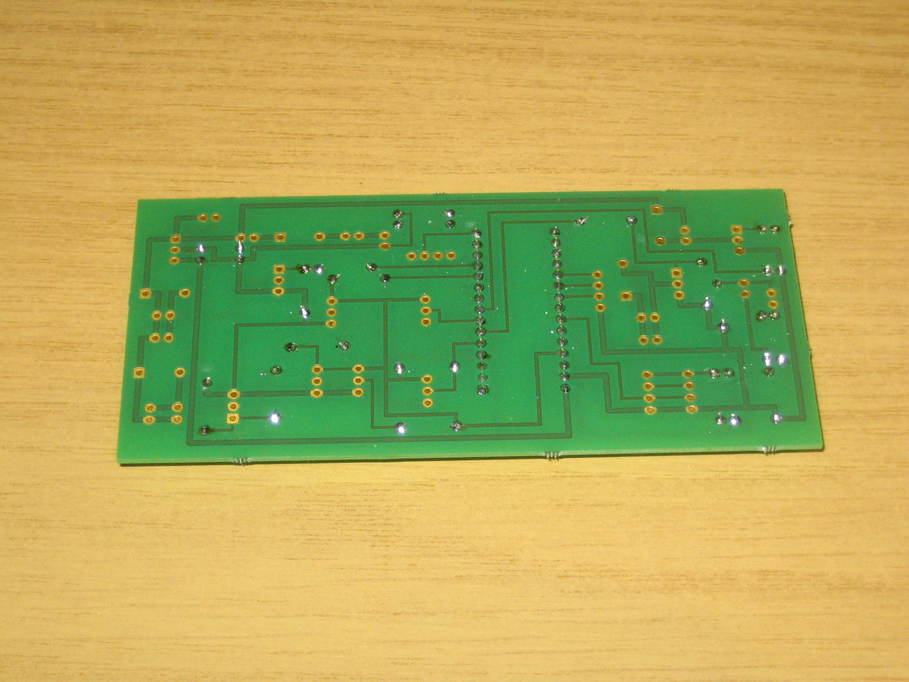
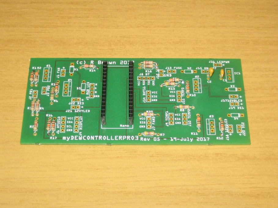
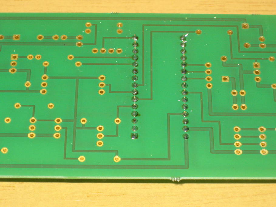
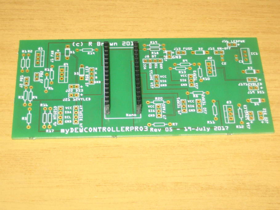
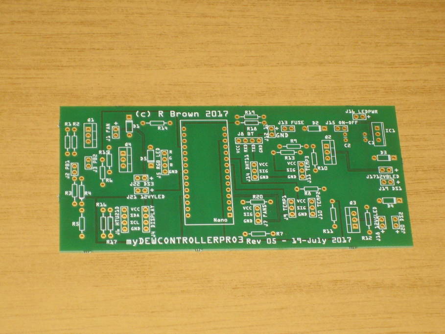
I’ve already covered the PCB in my earlier post.
Simple stuff first. Resistors, twenty in all:
4 x 330 ohm
1 x 1 Kohm
3 x 1.2 Kohm
1 x 2.2 Kohm
4 x 4.7 Kohm
6 x 10 Kohm
1 x 1 Mohm
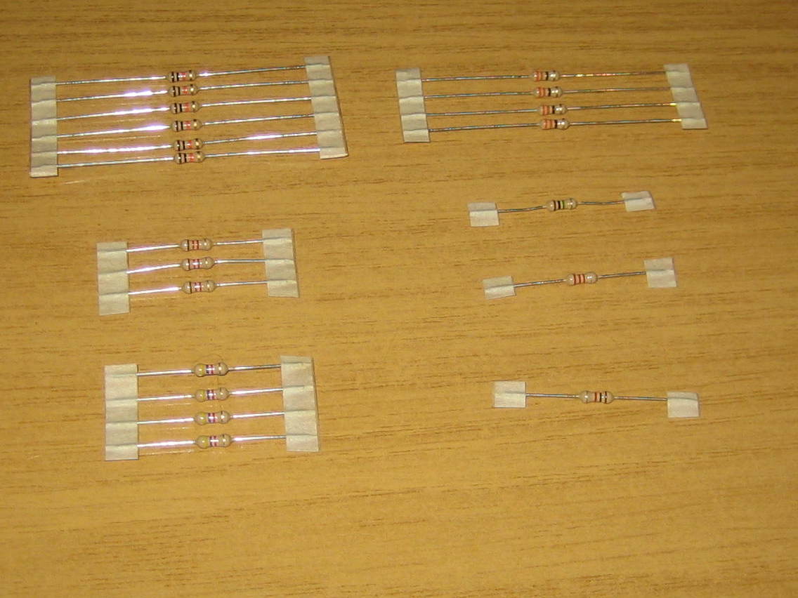
The documentation doesn’t suggest power ratings or tolerance, but the PCB design appears to suit 0.25W resistors and those are what look to be used in the build photos, so that’s what I went with. I assumed 5% tolerance would be ok.
Most of these I had anyhow, but those I was missing I bought from here:
https://www.ebay.co.uk/itm/High-Quality-0-25W-Resistors-100-330-470-1K-4-7K-10K-100K-OHM-UK-STOCK-New/200933857810
Capacitors. Just the two.
1 x 0.1uF
1 x 0.33uF
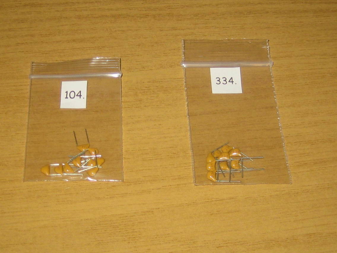
Bought from https://www.ebay.co.uk/itm/Monolithic-Multilayer-Ceramic-Capacitors-10-Pack-Choose-PF-NF-UF-Free-P-P/231332330771
Diodes
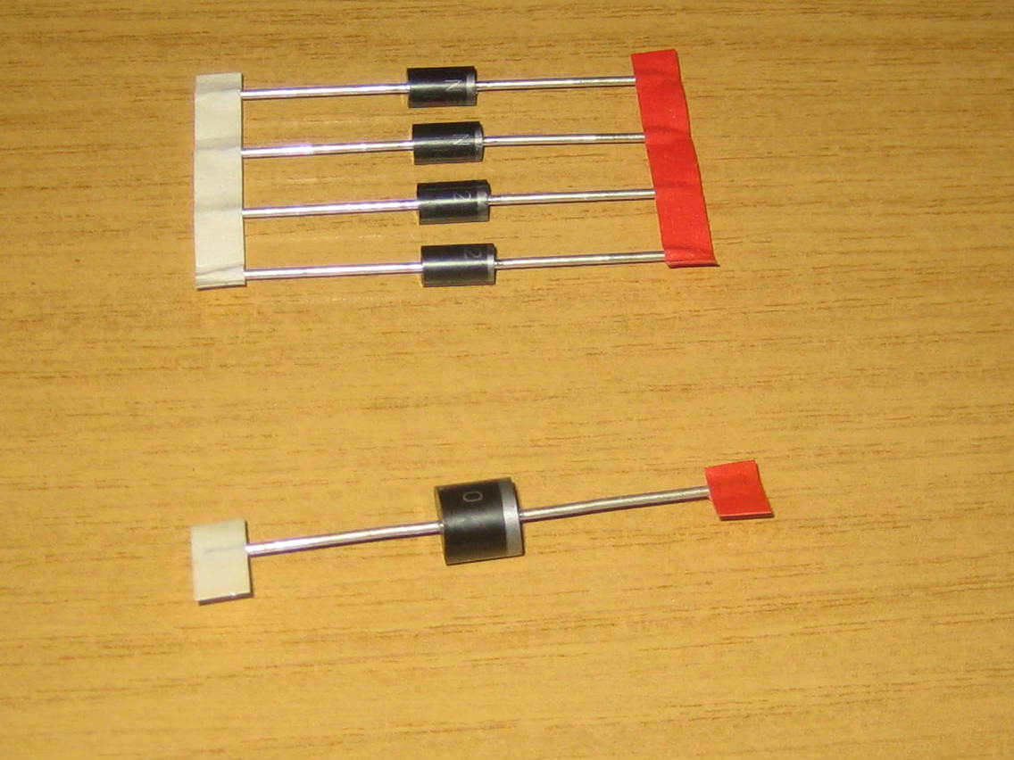
From https://www.ebay.co.uk/itm/1N5800-Series-Schottky-Diodes-1N5819-1N5822-Various-Pack-Sizes/152056021097 and https://www.ebay.co.uk/itm/5-x-10A10-Rectifier-Diode-10A-1000V/252434225368.
All of these actually have leads that I’d consider over large and don’t fit through standard PCB holes. With stripboards you can probably just enlarge the hole slightly, but with a prefab PCB an alternative solution needs to be found. For my first controller I bodged it, but this one I’m going to try to make a better job of it. I’ll return to this when I get that far.
LEDs
1 x 5mm Multicolour RGB LED model KY-016
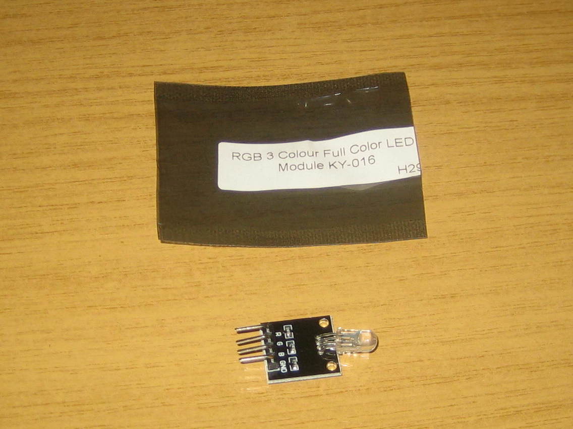
https://www.ebay.co.uk/itm/RGB-3-Colour-Full-Color-Led-Module-KY-016-For-Arduino-Raspberry-PI/263230411143
4 x 3mm 12V LED with resistor
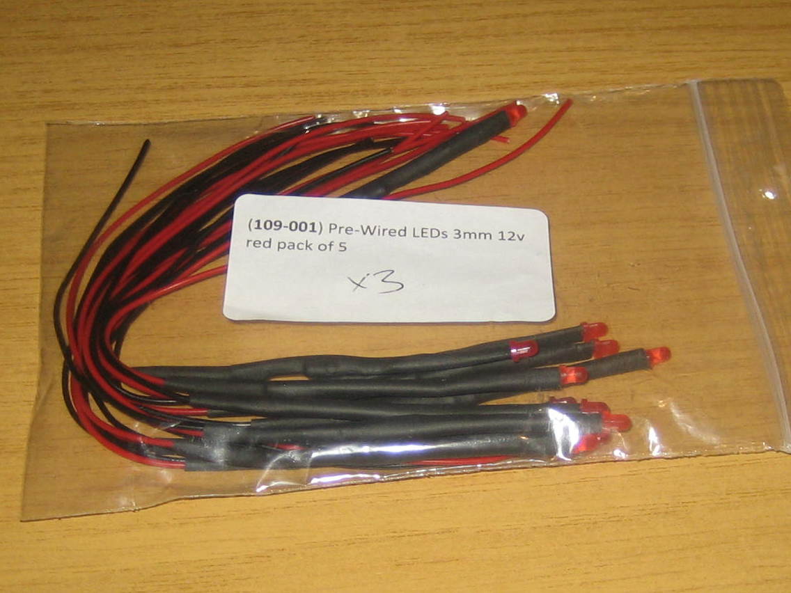
For the rest of the LEDs the documentation shows blue LEDs whilst the PCB seems to suggest one of each of red, green and blue, as well as a fourth for the power indicator. I just used red ones throughout. I don’t think anything is gained by using different colours really. The documentation also suggests these should come with a bezel, but I couldn’t find any so had to buy them separately.
https://www.ebay.co.uk/itm/Pre-Wired-3mm-LEDs-With-Resistors-Various-Colours-5v-6v-9v-12v-Pack-of-5/123912557473
Other ICs and similar
4 x FQP30N06L MOSFET — I didn’t need to buy these.
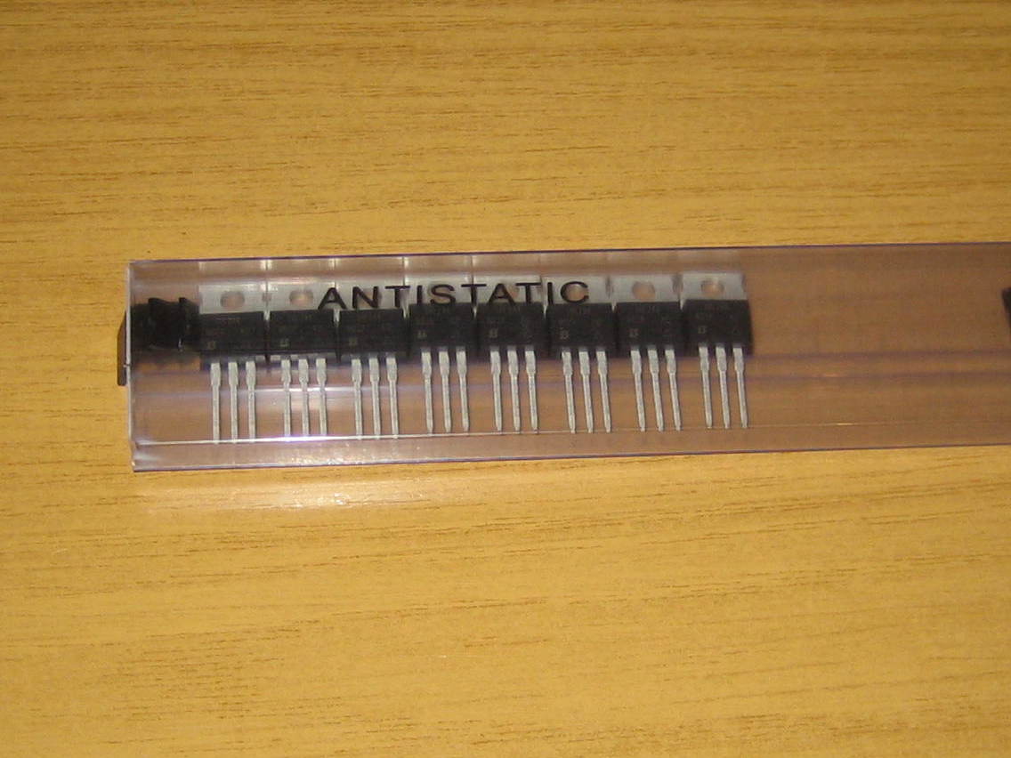
1 x LM7808 8V voltage regulator (TO-220 package)
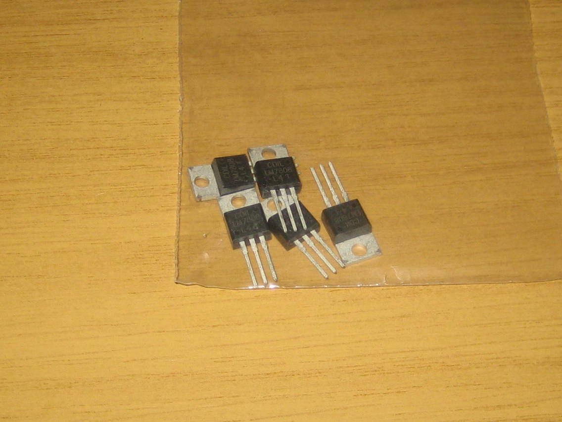
I got these from ebay, but the listing no longer exists
1 x DHT22 humidity sensor
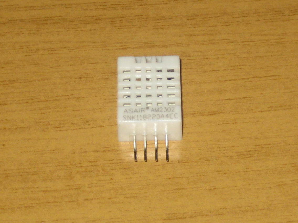
https://www.amazon.co.uk/gp/product/B06XF4TNT9/
1 x LCD2004 LCD module & I2C interface
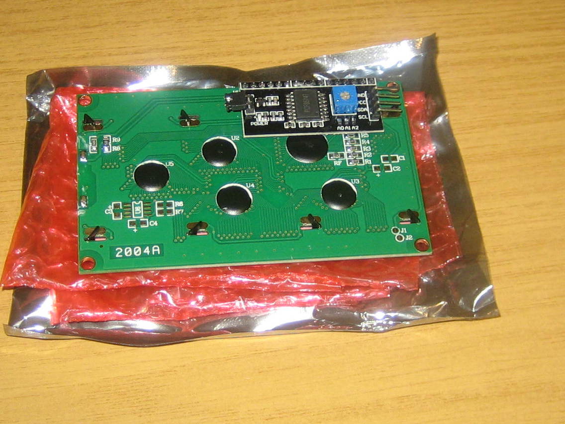
From here: https://www.amazon.co.uk/gp/product/B0725KXF99/
3 x DS18B20 thermal probe sensor
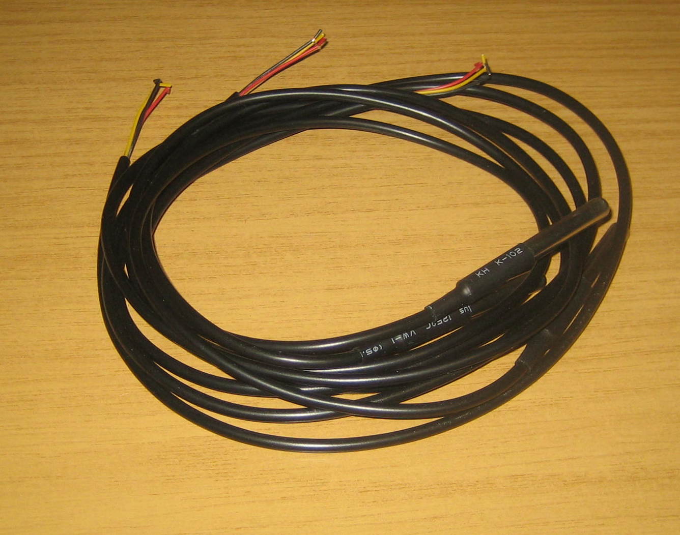
https://www.amazon.co.uk/gp/product/B075FYYLLV/
1 x DS18B20 thermal sensor in TO-92 package
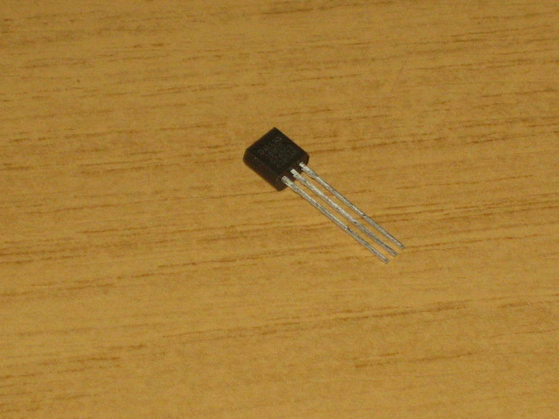
I already had some of these, but they should be easy enough to find on Amazon or Ebay
1 x Arduino Nano V3
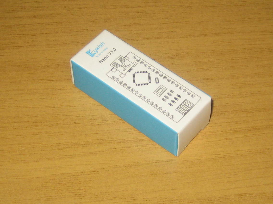
I bought as a pack of five: https://www.amazon.co.uk/gp/product/B07F8NW9JF/
And the other bits of hardware…
1 x USB B panel mount socket to mini USB plug
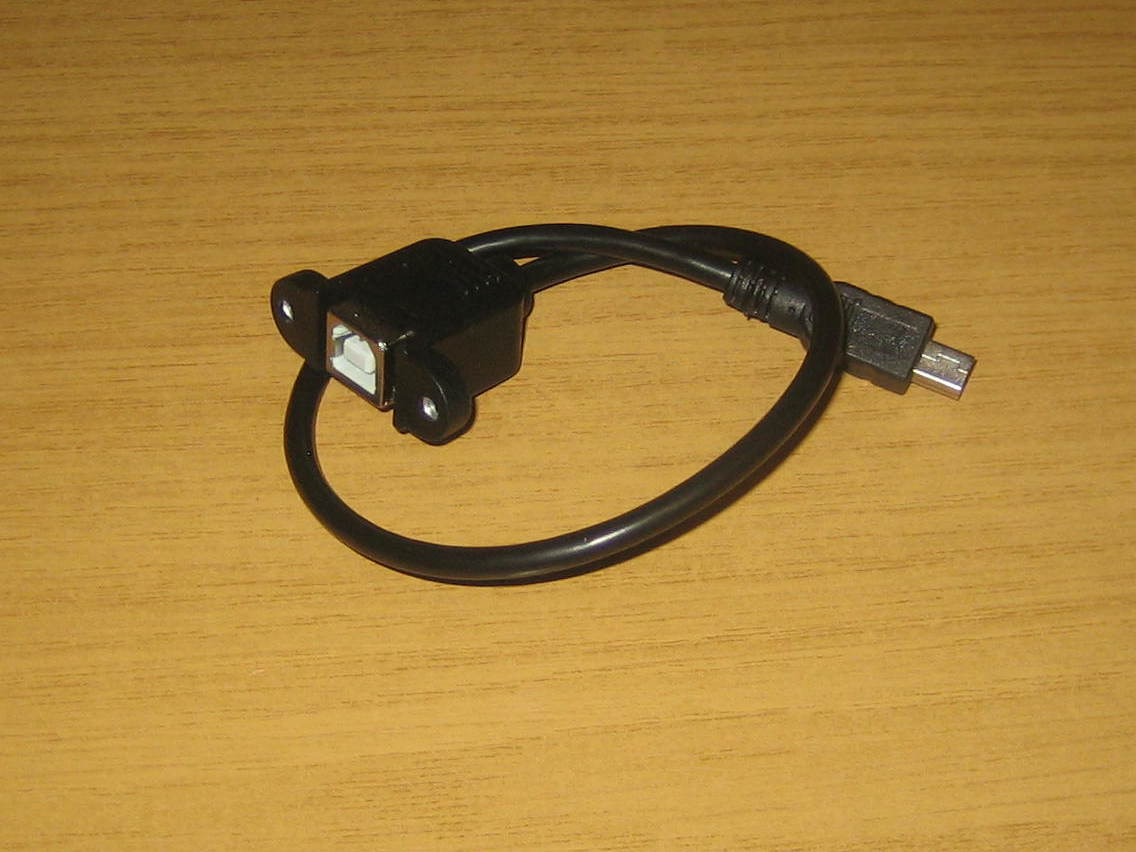
This is specified as a right-angle mini USB plug, but I couldn’t find any so I bought one with a straight plug. The case I designed has sufficient room for it, though it is possible to buy a right-angle converter (link also below). It only saves a couple of millimetres however.
https://www.ebay.co.uk/itm/30cm-Mini-5-pin-Male-to-USB-2-0-B-Female-Socket-Printer-Panel-Mount-Cable-Cord/231961140556
https://www.amazon.co.uk/Degree-Angled-Female-Extension-Adapter/dp/B015PRVI62/ref=pd_sbs_23_2/257-8654966-0092832
3 x RCA panel mount sockets
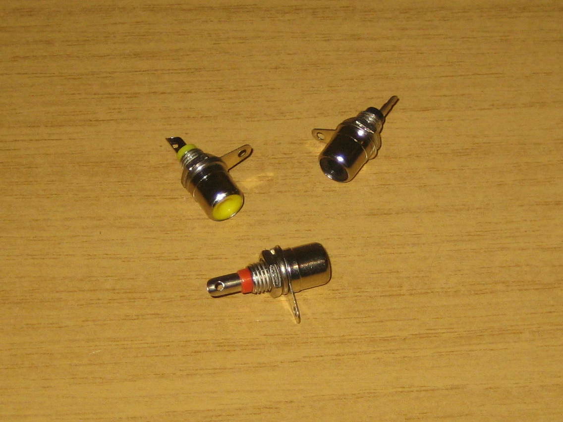
I had these already. They’re easy enough to find. For example:
https://www.ebay.co.uk/itm/RCA-Phono-Chassis-Panel-Mount-Socket-Connector-Red-White-Yellow-Black-x-8/222523856989
1 x panel mount power socket
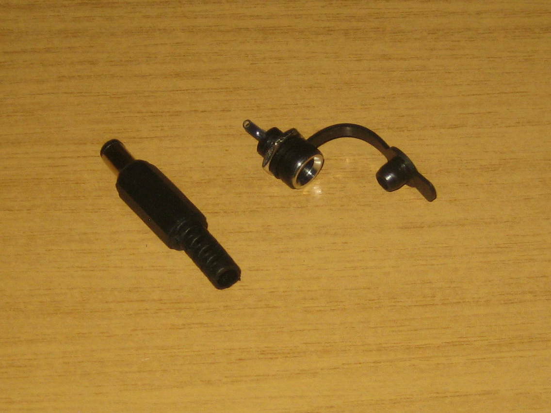
This is specified as 5.5mm with a 2.5mm centre pin. Pretty much all my other kit (mount, cameras etc.) uses a 5.5mm x 2.1mm socket though, so I used that size instead. I actually bought it with the matching plug so I can make up my own power lead to the correct length.
https://www.amazon.co.uk/gp/product/B07QNWSKN2/
1 x 5mm x 20mm panel mount fuse holder
1 x 6A 5mm x 20mm glass fuse
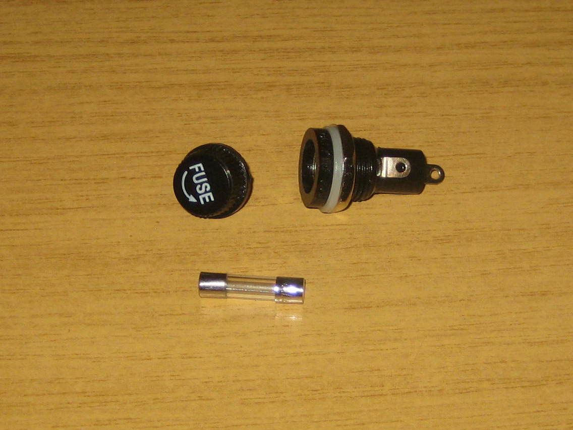
I already had the fuse holders. The fuses came from here:
https://www.ebay.co.uk/itm/Glass-Fuse-10-Pack-250V-5x20mm-Choose-from-available-values-Free-UK-P-P/261899073442
1 x 40mm 12V fan
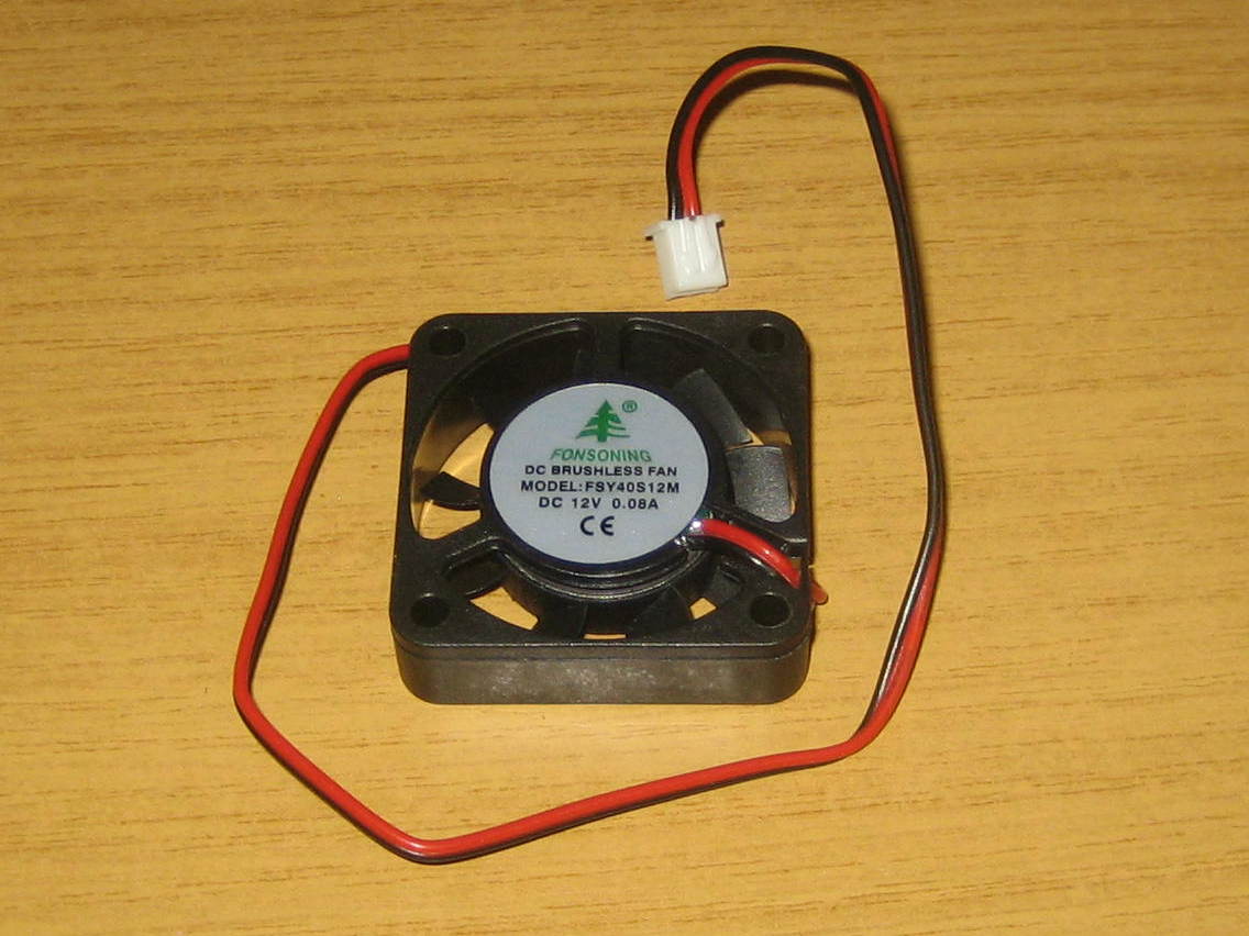
It’s claimed that you don’t really need this for the MOSFET build, but I chose to fit one anyway, just in case. The voltage regulator may well be happier for it anyhow.
https://www.ebay.co.uk/itm/4X-40mm-12V-Brushless-Computer-Case-System-Laptop-3D-Printer-DVR-Cooling-Fan-UK/153575881605
5 x TO-220 heatsink (with screw)
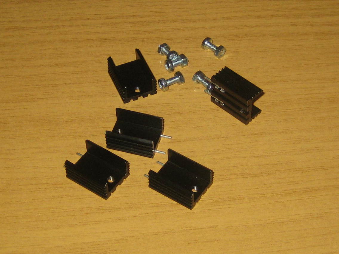
Again, these may not be required for the MOSFETs, but I decided to fit them anyhow (though slight modifications were required that I’ll talk about later). It’s probably a good idea to fit one to the voltage regulator regardless.
https://www.ebay.co.uk/itm/TO220-TO-220-Heatsink-Alloy-Various-Pack-sizes-For-Voltage-Regulators-etc-Pin/263988492509
5 x mica insulator and bush washer for TO-220 heatsink
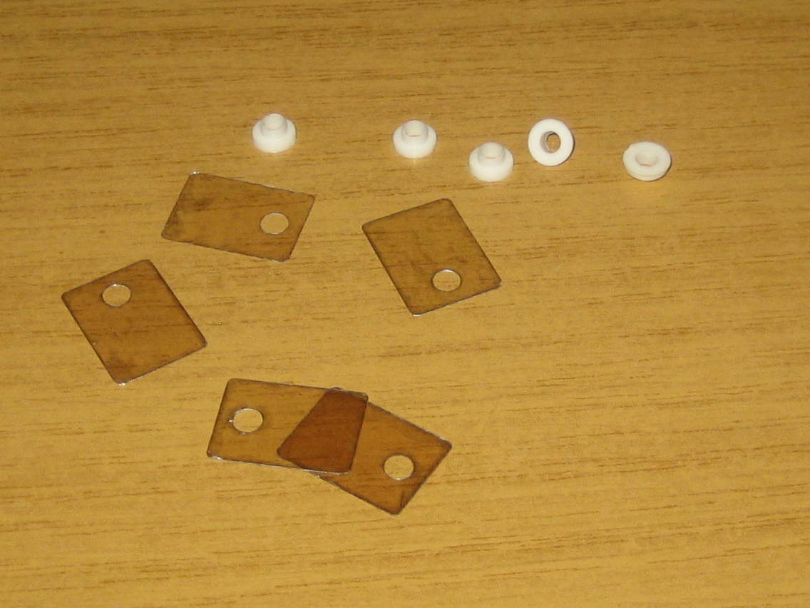
I got these from ebay, but the listing no longer exists. The mica piece insulates the heatsink electrically from the component and the bush for the screw ensures the screw can’t make electrical contact with the component either.
3 x 6P4C panel mount connector and plugs
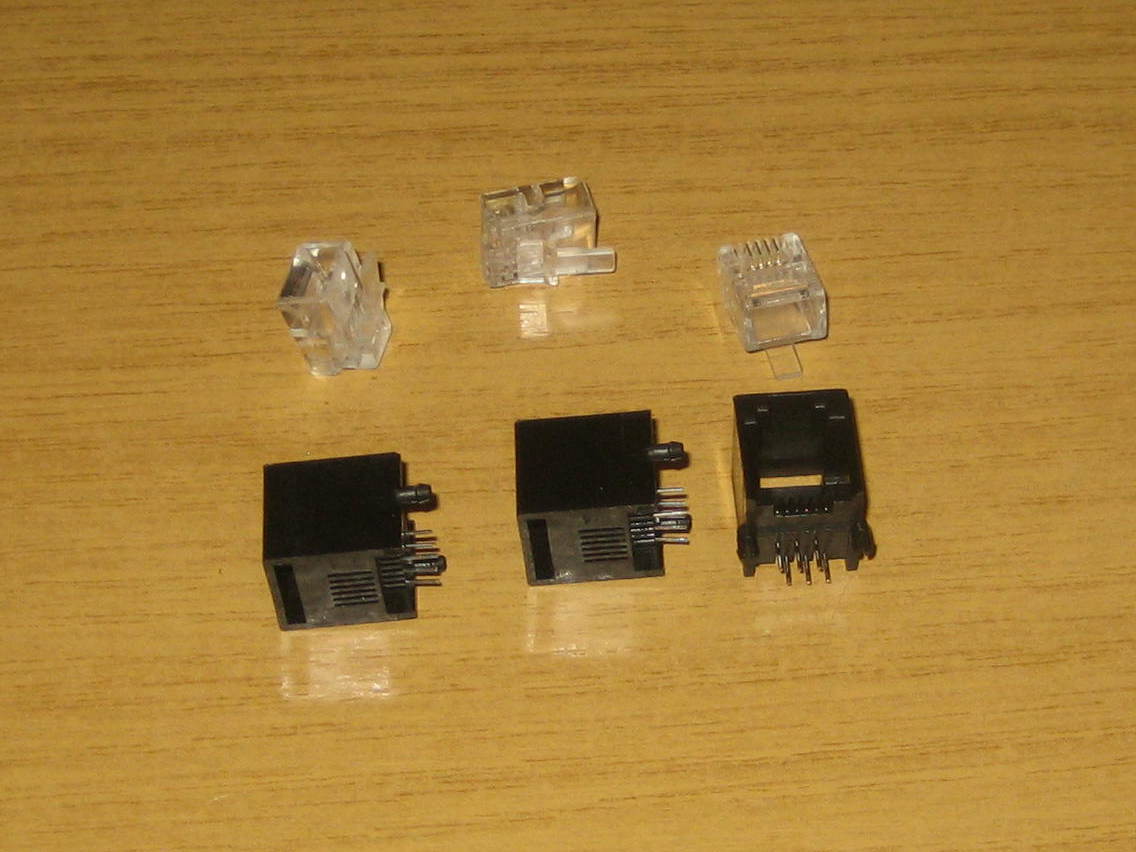
Sometimes also called an RJ11 or RJ12 socket/plug. In our case although it’s a six position (6P) connector, not all the contacts are required so we can make do with four (4C). 6P6C would work just as well. 6P2C won’t. If you don’t have the tool for crimping the plugs on and don’t wish to buy it then some other type of socket and plug would probably do just as well. I was tempted by 3.5mm stereo jack plugs and sockets but was warned by Robert Brown that they cause problems. I’ll return to this in a later post.
https://www.ebay.co.uk/itm/20x-RJ11-6P4C-Phone-Crimp-Connectors-Plugs-Ends-Cat3-ADSL-4-Pin-Fax-Telephone/254173063867
I also bought the sockets from Ebay, but the listing has now gone.
1 x SPDT mini toggle switch
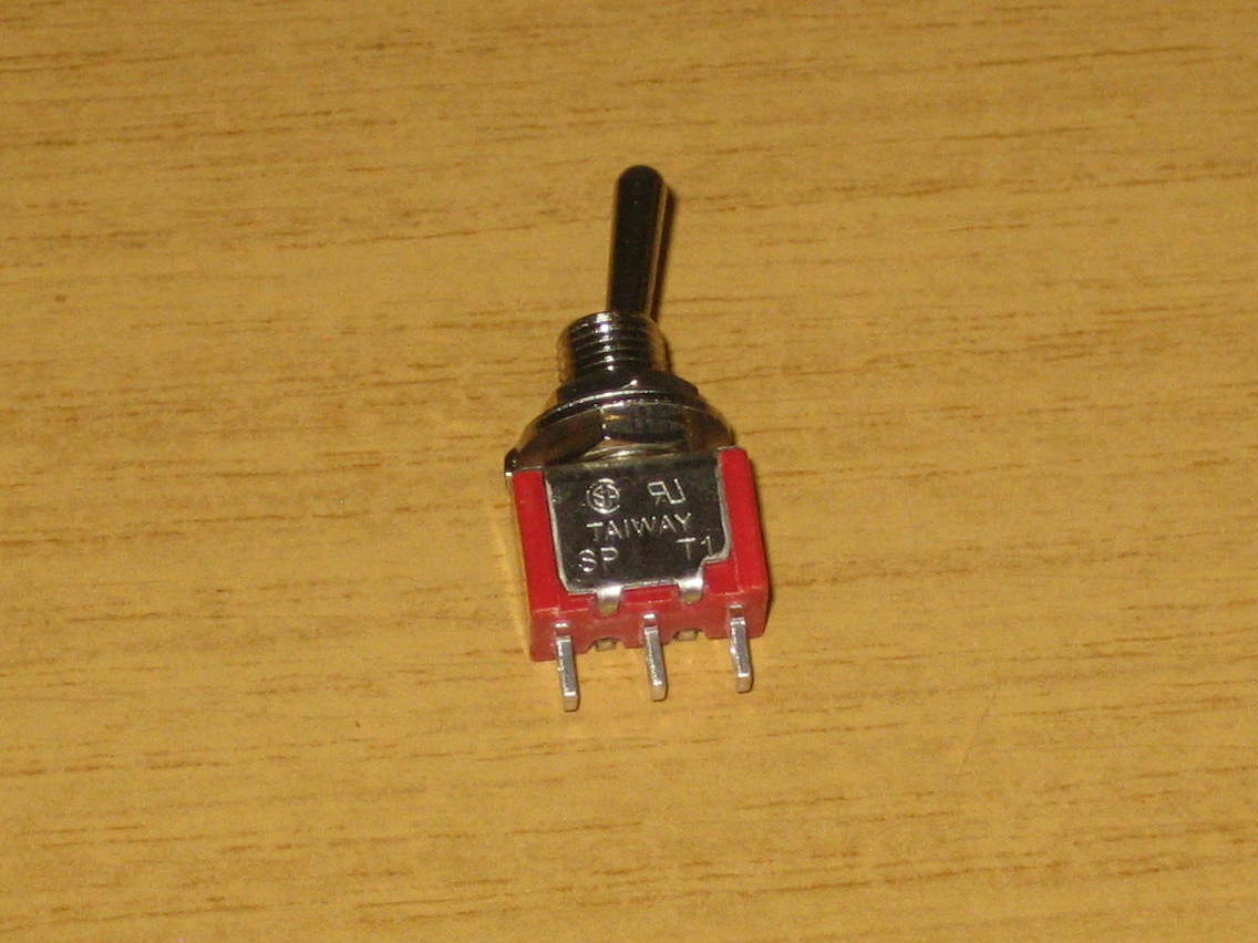
I already had some of these, still in their Maplin packaging! If you want to use the “Force heaters full on” feature, you’ll actually need three of these.
1 x 5mm LED bezel
4 x 3mm LED bezel
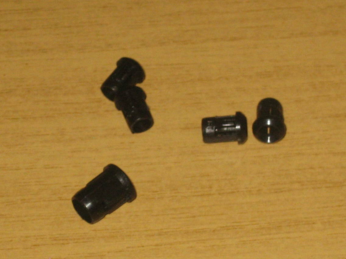
You can probably get away without using these, but it does make things look neater. The first set of 3mm ones I ordered (from elsewhere) were utter rubbish. These are a little better.
https://www.amazon.co.uk/gp/product/B07LD7W2PC/
https://www.amazon.co.uk/gp/product/B07H4M3N3D/
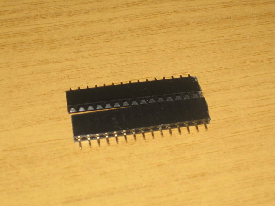
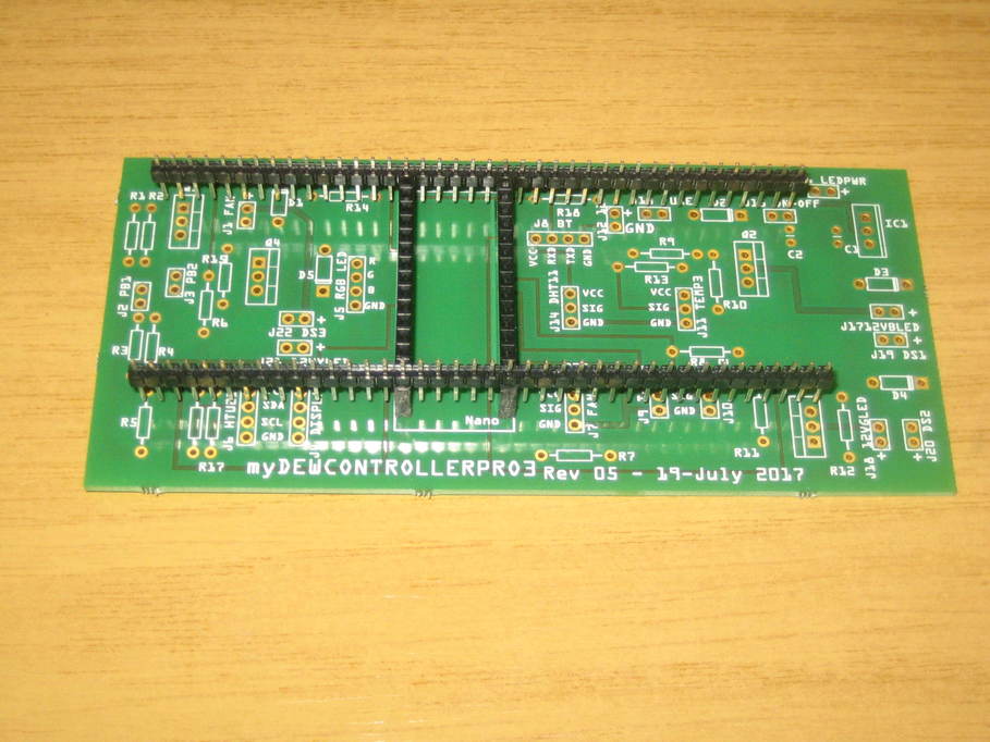
2 x female 15 pin headers (for the Nano)
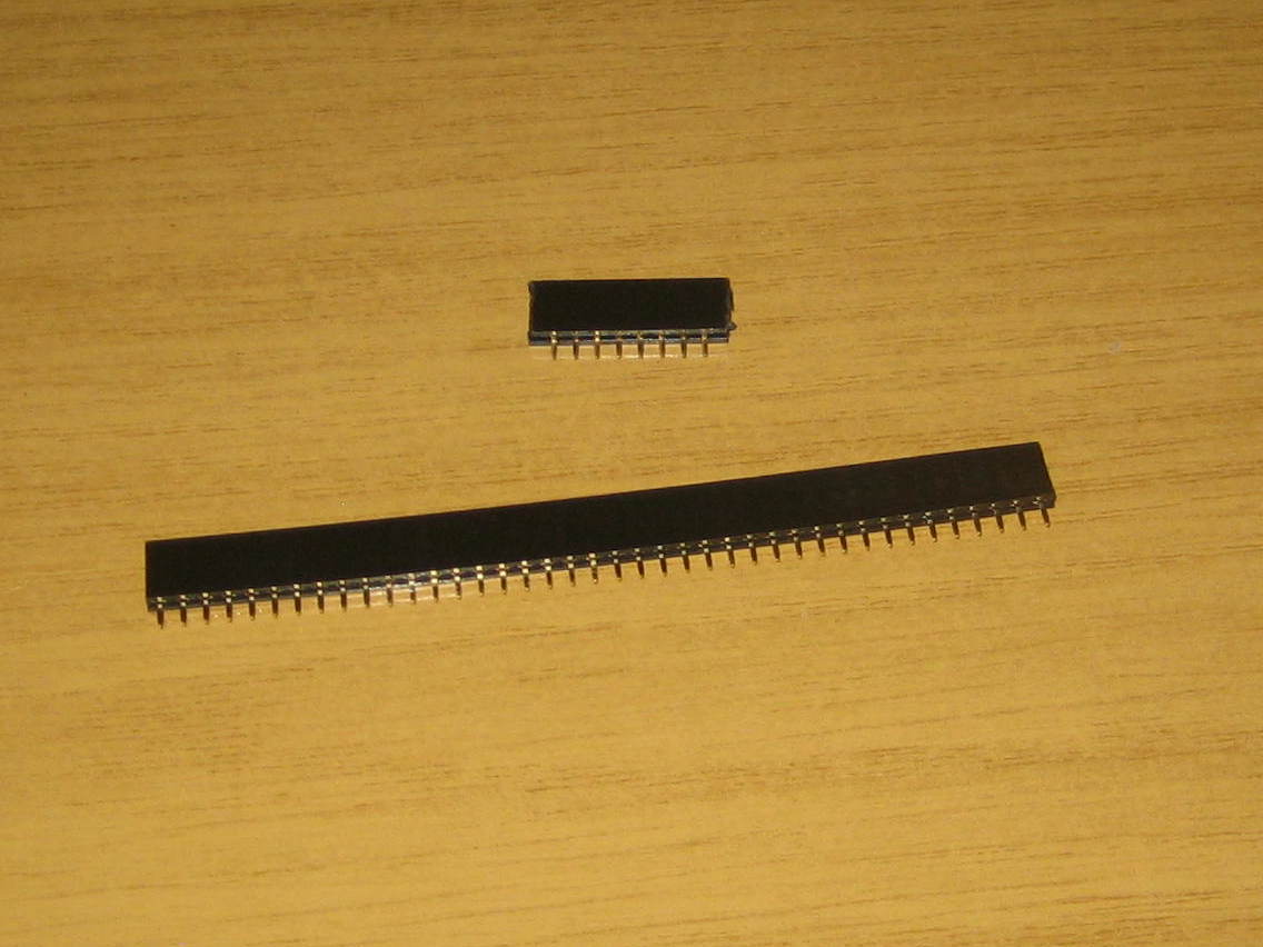
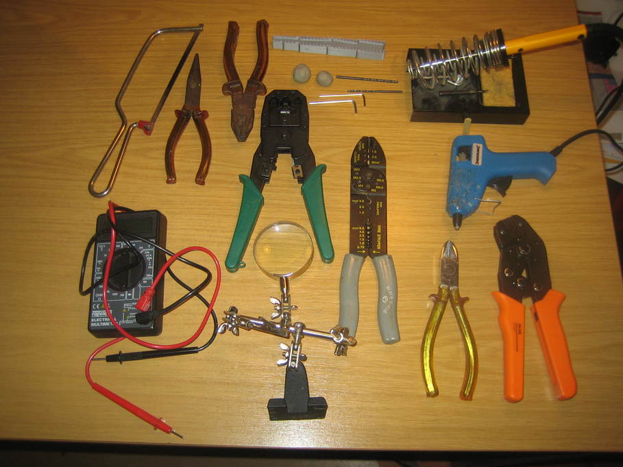
Using these means it’s easy to replace the Nano if it fails, but I couldn’t find any suitable 15-pin headers. Instead I bought longer ones and cut them down to size with the junior hacksaw. (It’s the black single female strip connector on this listing.)
https://www.ebay.co.uk/itm/263827548381
male pin headers
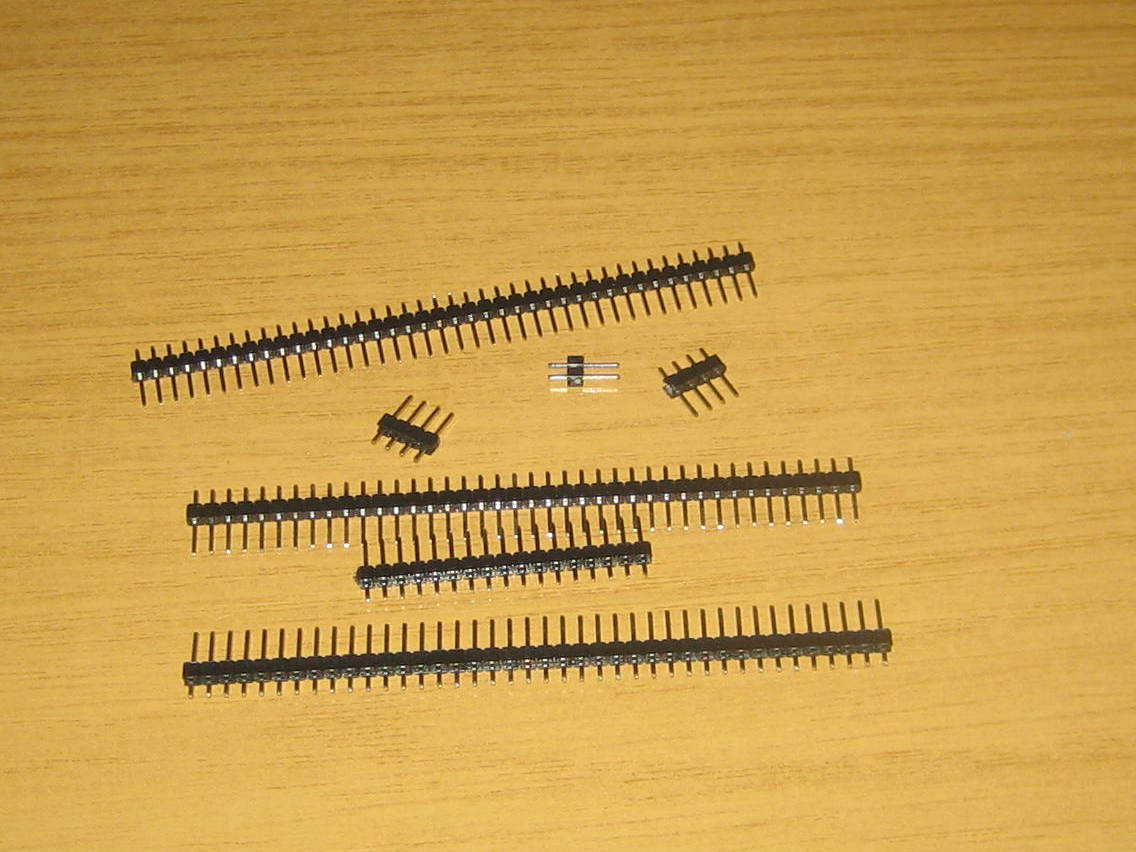
Quite a few of these are required for all the off-board connections and they can be bought from the link above — two of the male 40-pin headers should be sufficient. They can be cut to the right number of pins with a pair of side-cutters. However, that leaves you needing to make up the plugs to go on them, so instead I bought this, which includes the crimping tool, pins and plug bodies.
https://www.amazon.co.uk/gp/product/B07S1SDKSC/
If you don’t fancy making them up yourself at all, the following will do the job for most connections. I’d suggest you’d need six of the 20cm female to female strips.
https://www.ebay.co.uk/itm/Dupont-Ribbon-Cable-10-20-or-30cm-Male-Female-Or-Mixed-UK-Free-P-P/233180441032
But if you do go that route it may well be sensible to solder the power connector, power switch, fuse and dew strap wires direct to the PCB and not use pin headers at all.
Wire
I had some twin-core automotive wire that I think I bought from Amazon rated for 11A that I use to make up 12V power cables in the observatory. I also used it for the power connections inside the controller (power supply to PCB, power switch, fuse connection and dew controller connections). Where it was easier to have the two cores separate, I just stripped off the outer insulation to separate the wires.
Heatshrink
I have heatshrink in various sizes that I used on some connections in my first build. I may use it this time, but at the moment I don’t know.
Nuts & bolts
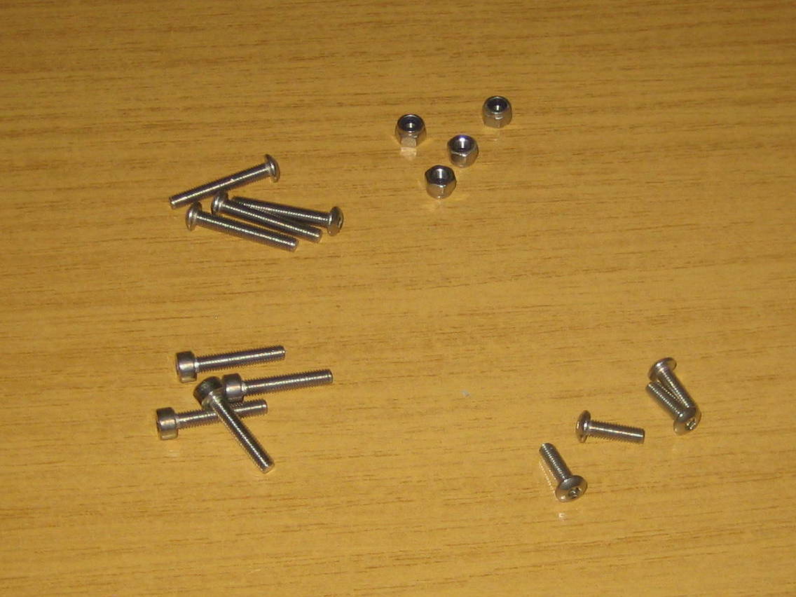
4 x M3 stainless 16mm hex cap screws
8 x M3 stainless nyloc nuts
Just used for mounting the fan (four of the nuts are used for fixing the LCD display). Nyloc may be overkill, but given that I was going to be using them on a fan I decided I’d err on the side of caution.
https://www.ebay.co.uk/itm/M3-3mmØ-CAP-SCREWS-A2-STAINLESS-STEEL-HEX-SOCKET-ALLEN-KEY-BOLTS-DIN-912/361582679814
https://www.ebay.co.uk/itm/NYLOC-NYLON-INSERT-LOCKING-NUTS-A2-STAINLESS-STEEL-M2-5-3-4-5-6-8-10-12-16-18-20/150783000310
8 x M3 stainless 20mm button head hex screws
For fitting the display, and in my case screwing down the lid of the case. I’d expect a purchased case to come with all the necessary screws for the lid.
https://www.ebay.co.uk/itm/BUTTON-HEAD-SCREWS-ALLEN-KEY-SOCKET-DOME-BOLT-A2-STAINLESS-STEEL-M3-M4-M5-M6-M8/362765268288
2 x M3 stainless 10mm button head hex screws
For fitting the USB panel mount socket (mine were M3 threaded, though still a bit awkward to fit)
https://www.ebay.co.uk/itm/M3-3mmØ-BUTTON-HEAD-SCREWS-ALLEN-KEY-HEX-SOCKET-DOME-BOLTS-A2-STAINLESS-STEEL/181024489629
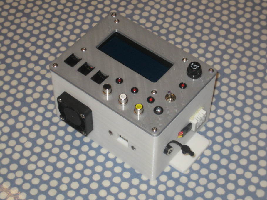
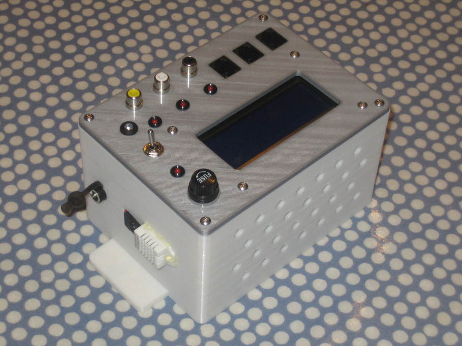
Case
As I’ve already mentioned, I printed my own case. The docs specify a case measuring 163 x 100 x 50mm, but I reckon that’s really too small now. The design in the documentation build photos doesn’t have as many components as the current version and even so many of the switches and external connectors are really tight up against each other or even overlapping. Slightly bigger would probably be better.
If you want to put the sensor and/or dew heater connectors on the end of the case rather than the top, having removable end sections might be useful to allow room for fingers and tools when fitting the sockets. I think someone posted on SGL saying they’d used a case with a clear lid, meaning the LCD could be completely sealed inside the case and still be readable.
Also note that if you’re going for the prefab PCB, it doesn’t have any mounting holes, so the case needs to provide some mechanism for holding the PCB in place. If you’re using stripboard obviously holes can be made to suit.