Robert Brown Focuser Controller build, step by step #7

I think it must be a short somewhere between some of the tracks. This evening I’ve built a new board from the ground up, plugged in the same Nano and stepper driver and it’s running “blink” fine. A small part of the layout is slightly different from the first one as I realised I could do it a little more neatly, but the circuit is clearly the same. I guess I just need to get the big magnifying glass out so I can check things over better.

At least I have something I can continue working with now.

Posted in Astro Equipment, Astronomy, Projects | Tagged , | Leave a comment

Robert Brown Focuser Controller build, step by step #6

Having finished the circuit board I plugged in the Nano and motor controller and connected it to a USB port (without any other power source connected). The power LED lit on the Nano, but nothing else happened and I wasn’t able to connect to upload a sketch. Unplugging the Nano from the board allows it to work exactly as expected. I can upload the “blink” sketch and it runs ok. Plug the Nano back in and the sketch doesn’t start and there’s no response when attempting to upload.

I can’t find any obvious problems with the circuit or my soldering so far, but I have to assume that either the 12V supply is required in some way that isn’t obvious to me or that there must be some issue with my soldering that I just can’t see.

As stealing the eyes of a teenager tends to be frowned upon I’m thinking my best option at this point may be to build a second board and test the Nano out at each stage to see what happens. The only other thing I can think of for the time being is to connect up the 12V supply and check if any magic smoke comes out, but I’m not so keen on that approach whilst there are still other things to try. I could perhaps attempt to build the circuit on a breadboard, but I’m not convinced there’d be room.

Posted in Astro Equipment, Astronomy, Projects | Tagged , | Leave a comment

Robert Brown Focuser Controller build, step by step #5

I now have almost all the components in place.

The large diode at the top left wasn’t in the original plan I worked from. That’s the reverse voltage protection diode. Obviously no-one, least of all me, is ever going to connect the power the wrong way around anyhow, are they? The leads on this diode were larger than the hole diameter, so I ended up buying some small diameter drills from Amazon and enlarging two of the holes to about 1.5mm so it would fit.

The top right I had to reorganise a little. Fitted around the top of the header for the Nano is the diode that protects the voltage regulator. The two resistors and the third diode form the voltage sensing circuit that means the Nano won’t try to drive the motors unless 12V power is connected. To make that all work I had to move one of the capacitors for the voltage regulator and make another cut in the track feeding the Vin pin on the Nano (which is bridged by the diode).

All that remains now is the voltage regulator itself, which will fit at the top on the very right hand edge.

As I’m not using some of the other features of the focuser controller such as the temperature sensor and the OLED display, there’s quite a bit of space free in the middle of the board. When I make the next one I might move the Nano to the left two or three columns to make a bit more space on the right hand side for the additional components at the top right.

Posted in Astro Equipment, Astronomy, Projects | Tagged , | Leave a comment

Robert Brown Focuser Controller build, step by step #4

In the end I couldn’t find a single application that would do what I wanted, so I just decided to start cutting tracks and see where I ended up 🙂

And then spent a happy hour or two soldering in all the headers,

Finally adding all the string to join the various bits of track together.

Oh, I put the two capacitors in for the voltage regulator too.

Next is a bit of testing to make sure I don’t have any bridged tracks where I don’t want them. There is actually one place where I deliberately bridged the tracks with a lump of solder. The DRV8825 “sleep” and “reset” pins are next to each other and both clamped to the 5V output of the Nano, so I just dragged a lump of solder across the tracks they use.

Once I’ve checked the soldering over there’s not a lot left to do — the resistor network for the pushbuttons, current-limiting resistor for the buzzer, two resistors and a diode for the supply voltage sensing, another couple of diodes, a capacitor and the voltage regulator and I think I’m done. I may need to break a few more tracks to fit all of those in, but that’s not a problem.

Posted in Astro Equipment, Astronomy, Projects | Tagged , | Leave a comment

Robert Brown Focuser Controller build, step by step #3

All the parts that I didn’t already arrived, so I need to get on with laying out the stripboard. I found what looks to be quite a handy tool for doing that last night (it’s probably simple enough to do by hand, but having something else check my work is always welcome) called VeroRoute. It appears to be intended for more general PCB layout, but can do stripboard as well and can check for sections that should be connected but aren’t, or vice-versa.

Posted in Astro Equipment, Astronomy, Projects | Tagged , | Leave a comment

Robert Brown Focuser Controller build, step by step #2

The first parts have arrived: a pair of NEMA17 stepper motors with 27:1 reduction gearboxes.

Posted in Astro Equipment, Astronomy, Projects | Tagged , | Leave a comment

Robert Brown Focuser Controller build, step by step #1

I’ve done a bit of reading and messing about with GIMP and this is what I think I plan to build:

I believe I understand pretty much all of the circuit now. The resistor network to the left of the Nano is just for the buzzer, manual movement buttons and LEDs. C1, C2 and the 7808 provide the 8V regulated supply for the Nano. D3 stops the Nano trying to push 5V backwards through the regulator if there’s no 12V power. R14, R16 and D2 form a power detection circuit (so the code won’t try to step the motors and get confused about its position if there is no 12V power). D1 is reverse voltage protection and C4 is apparently required across VMOT and GND on the DRV8825 for it to work.

Posted in Astro Equipment, Astronomy, Projects | Tagged , | Leave a comment

Darkstar restoration, part 3

Whilst sorting out a holesaw to enlarge the focuser port I made a decision regarding which focuser I was going to use and then set to with FreeCAD to design a new mounting plate for it. I’d measured the outside circumference of the tube as 1122mm which gives an outside radius of about 178.6mm. I needed that to create the curved mating face of the mounting block. A short while later courtesy of my 3D printer I had this:

A quick test gave a good clean fit to the outside of the tube, but I needed some new longer bolts for fitting the focuser so ordered them (in stainless steel) via ebay, which I’ve always found a great place for getting nuts and bolts in small volumes.

Posted in Astro Equipment, Astronomy | Tagged , | Leave a comment

Darkstar restoration, part 2

The new world in which we find ourselves has brought other priorities to the fore over the last few months, but now things seem to be settling down a little, at least for a while, it’s time to get back to spending some time writing…

Back at the tail end of February I was starting to fix up my Darkstar 12″ dobsonian and the next step was to replace the focuser. I had a couple of choices, but the first step was to remove the old one and see what things looked like underneath. As it turned out, the mounting plate appeared to have been sealed using blutak or something similar.

The hole appeared to be just over 50mm in diameter, so probably actually two inches. Whichever focuser I upgraded to needed a hole of at least 60mm and preferably closer to 65mm, so the next step was to find a holesaw of a suitable size.

Posted in Astro Equipment, Astronomy | Tagged , | Leave a comment

Darkstar 12″ f/6 dobsonian telescope restoration

As I posted previously I am now the keeper of a 12″ f/6 Darkstar dob that’s in need of a reasonable amount of work to get it usable again. Having left it to loom over the power tools in the workshop for a few days I thought I’d start with a summary of things that need doing and perhaps a few improvements.

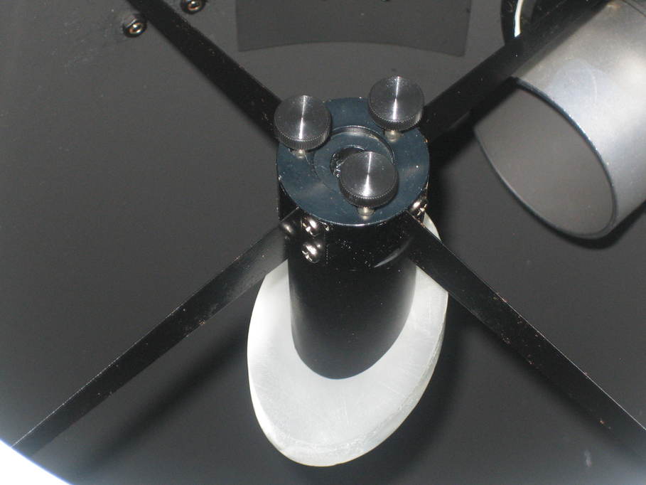
The first thing to fix is the secondary assembly. This is what remains of it:

At some point the original secondary mirror appears to have taken a swan dive off it’s mount and crashed into the primary below, getting badly damaged in the process. One of the spider arms has broken free of its retaining weld (perhaps it wasn’t a very good weld in the first place because the arms appear to be cut from a sheet of galvanised steel). The arm on the right is also missing the retaining nut (another weld failure, most likely). There’s what appears to be a screw clamping the secondary height adjuster in place, but as things turn out it looks to be a bit of threaded bar with a nut welded onto the end (which has also failed). The mirror mount itself (a piece of plastic tube cut at 45 degrees) I do not intend to re-use. I don’t feel it provides a large enough area for fixing the mirror in place.

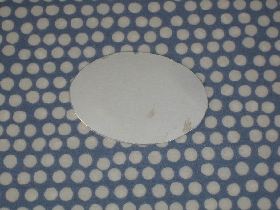
Someone kindly donated a new secondary to the project, currently buried in cotton wool.

And the previous owner made up a bit of aluminium to fix it to.

The rest of the assembly I’m still debating over. I could strip back the paint and re-weld the spider arm and a new nut, and fix up the clamp screw. Another kind donor supplied a somewhat unusual-looking spider:

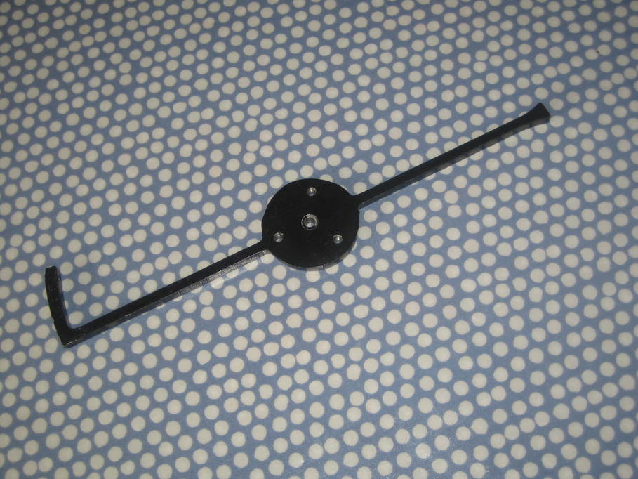
I could use that instead, but it’s actually a little short so I’d need spacers and I think that might make a bit of a mess with diffraction spikes.

Another possibility is to cut the remaining arms off and fit them to a piece of round aluminium bar that has one end cut at 45 degrees, similar to the way that Skywatcher do it on their OTAs:

then fix threaded rods to the other ends of the arms and use knurled wheels on the outside of the tube as adjusters.

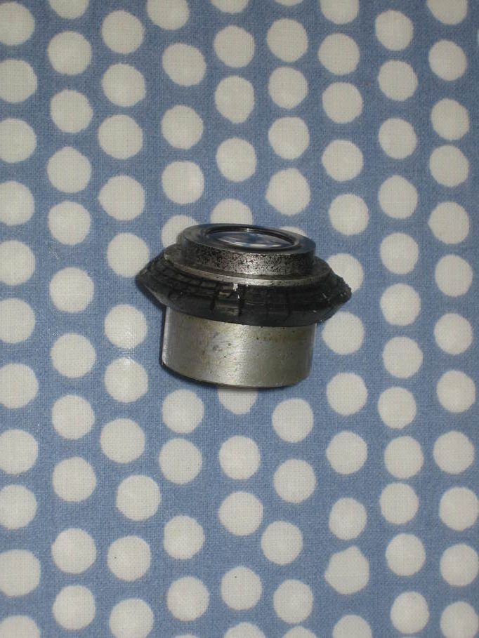
The finder is an “interesting” bit of kit, made from a binocular objective (and perhaps eyepiece as well?)

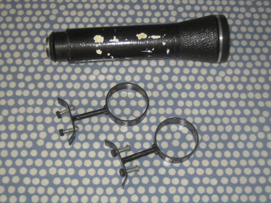
The tube forming the main barrel of the finder has a neat little set of crosshairs made in the end.

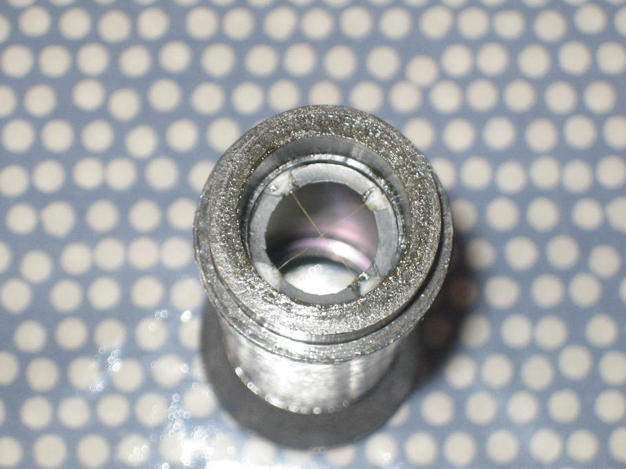
I assume they have to be at the focal plane of the primary lens otherwise they’re not in focus. They eyepiece itself has some odd sort of seal around it that is badly perished. Or very well perished, depending on how you look at these things.

I’m quite taken by the Heath-Robinson engineering, but I can’t help thinking that a standard 50mm finder would just be so much simpler. Perhaps a right angle model, given the size of the OTA. It has also crossed my mind that I could perhaps fit something like an ST80 as a finder. On a scope of this size that might work fairly well.

The coating of the primary mirror has some damage from the secondary hitting it, but for the moment all I propose to do is to give it a gentle wash.

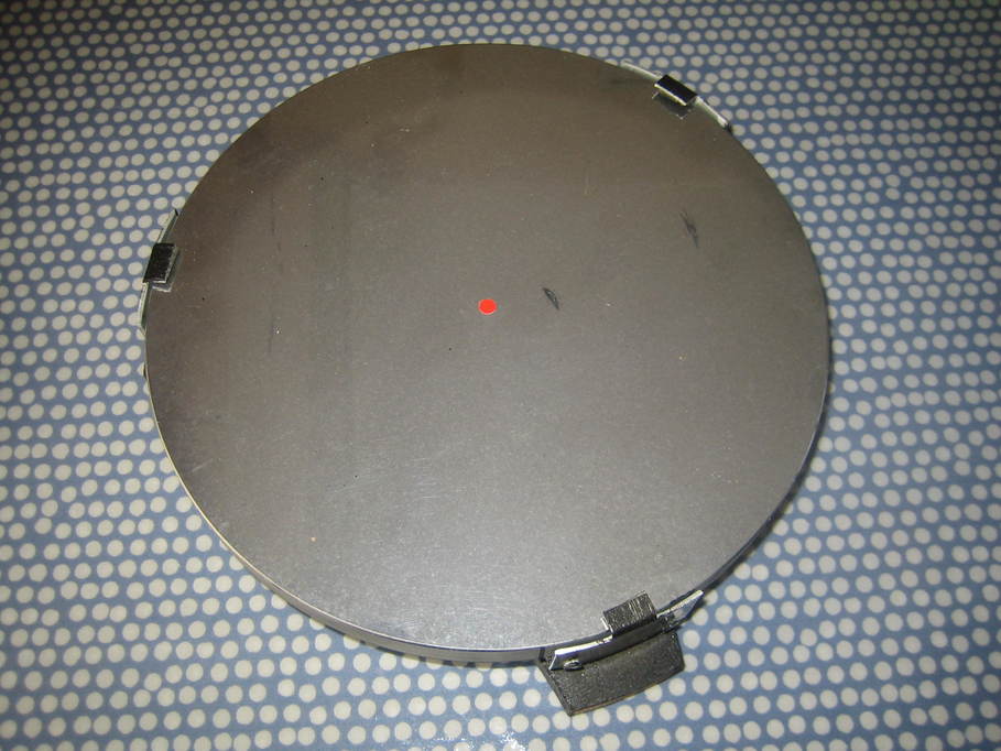
I suspect the damage closest to the centre spot will be covered by the secondary and not affect the performance at all, but we’ll see once it is back together.

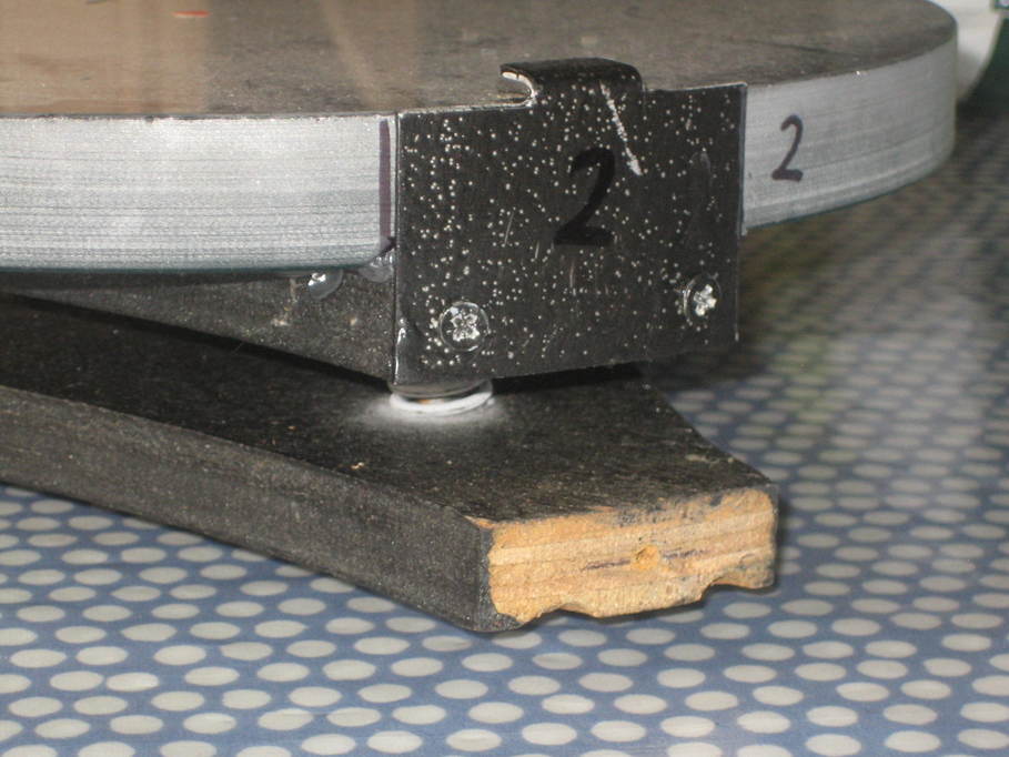
I’m not hugely wild about the plywood cell and mirror clips, but for the time being I think they can stay. Once I have it all back together and usable I’ll have another think about that.

And the last thing I think needs immediate attention is the focuser. The existing one is a bit basic, to say the least.

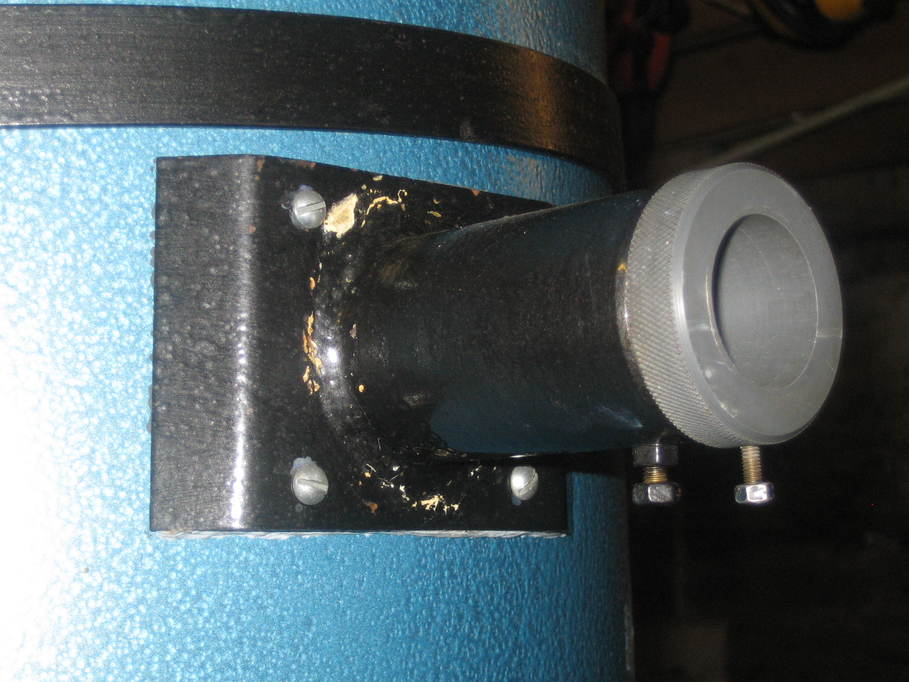
A dig around in the observatory came up with this as a possible replacement (which would also allow 2″ eyepieces to be used).

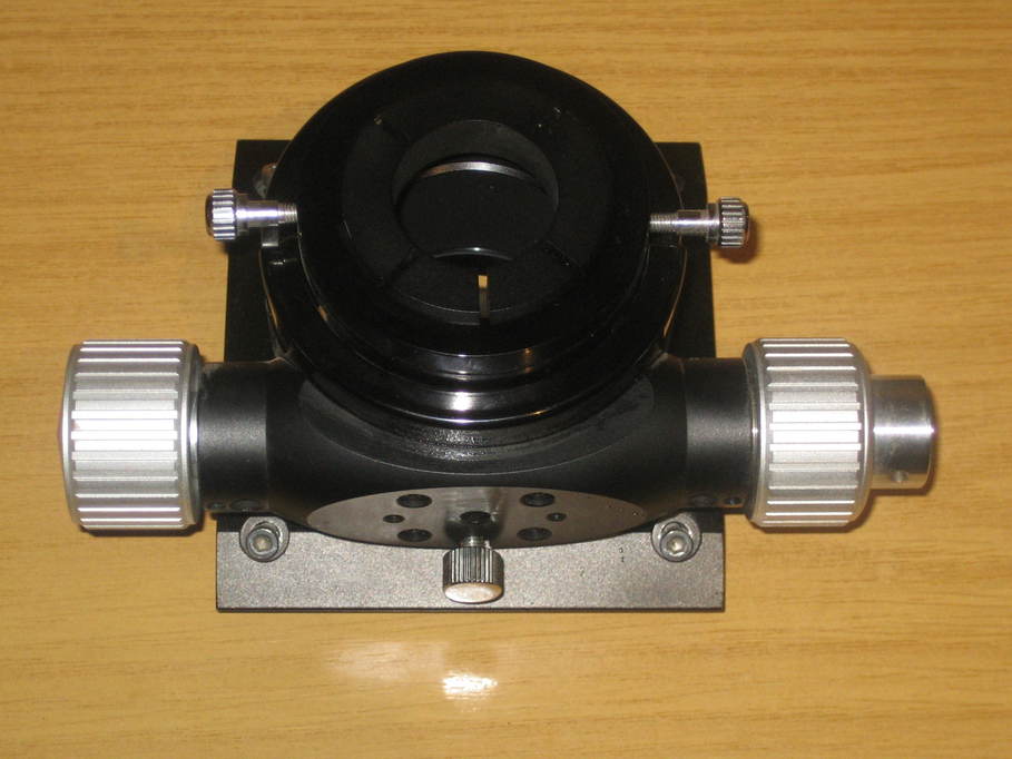
It needs a new slow-speed knob, but I can probably 3d-print one, or turn one from a piece of brass. I think I’d also need to 3d-print a base to fit the tube that I could fit this onto, but that would at least prevent light leakage from the sides. Someone appears to have done that with the existing one by filling the gaps with something like blutak.

The other thing the previous owner gave me was this:

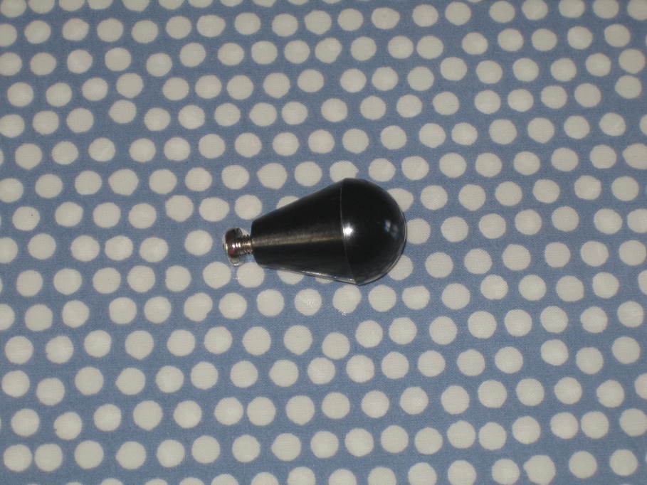
A dob knob. No self-respecting dob should be without one.

Other things I need to think about are probably a barrow for moving it around, as whilst it’s not particularly heavy the size does make it a little awkward, and some sort of restraint or lock to stop the tube moving in storage (there’s part of a chain still fixed to the rocker box that might have been for that purpose). Oh, and a pair of platform sole observing boots, so I can reach the focuser when the OTA is pointing at the zenith 🙂

For the time being I think that’s it. People have suggested other ideas for improvements, but I think returning it to use should be the first target. The focuser and a 50mm finder shouldn’t be too hard to sort out so I may well start there whilst I cogitate on the issue of the secondary assembly a little further. The mirror I can deal with last. I’ll also keep my eye out for anything along the lines of a used ST80 for sale.

Posted in Astro Equipment, Astronomy | Tagged , | 2 Comments