
I’ve done a bit of reading and messing about with GIMP and this is what I think I plan to build:
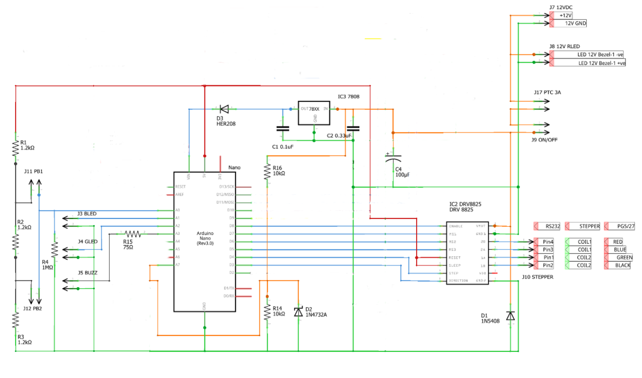
I believe I understand pretty much all of the circuit now. The resistor network to the left of the Nano is just for the buzzer, manual movement buttons and LEDs. C1, C2 and the 7808 provide the 8V regulated supply for the Nano. D3 stops the Nano trying to push 5V backwards through the regulator if there’s no 12V power. R14, R16 and D2 form a power detection circuit (so the code won’t try to step the motors and get confused about its position if there is no 12V power). D1 is reverse voltage protection and C4 is apparently required across VMOT and GND on the DRV8825 for it to work.