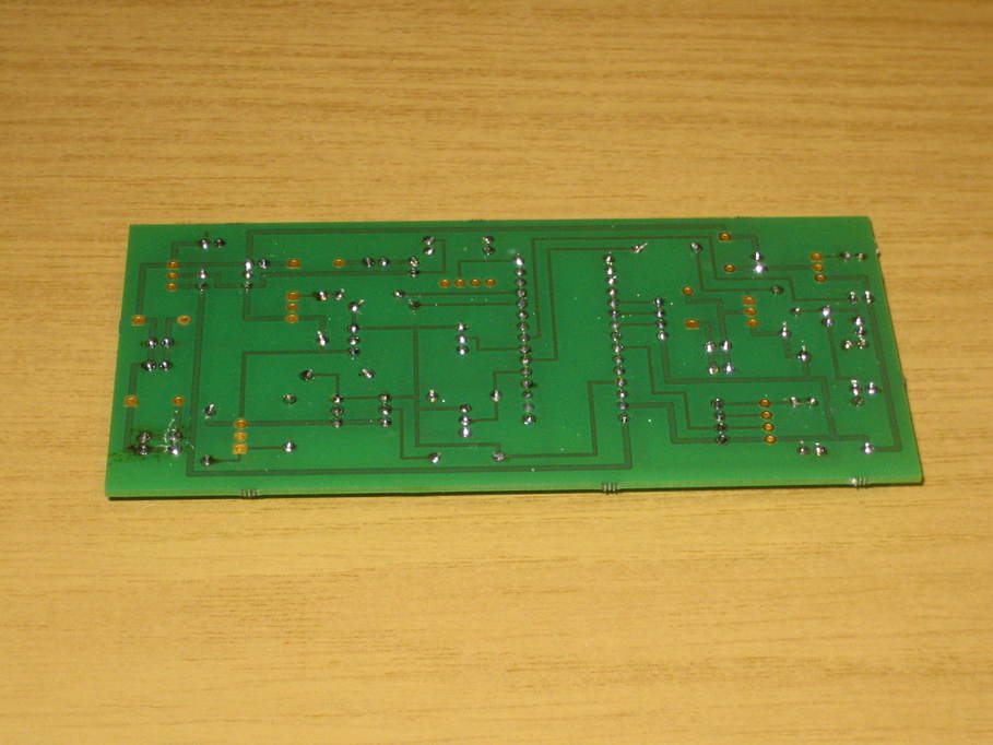
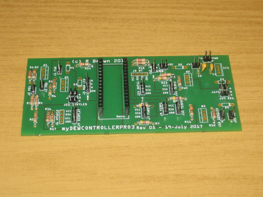
All the pin headers that I’m going to use are now in and there aren’t too many holes left, especially as the two four-pin headers that are left won’t be used (the ones for the Bluetooth connection and the HTU21D humidity sensor).


For the pin headers I used much the same method as for the resistors: put a number in place and then gently press a flattened piece of blutak down over the top to keep them all in position whilst the board is flipped over and everything soldered into place.
As I mentioned before, the five diodes have leads that appear to be 1.1mm in diameter and are too big for the holes in the PCB. In my previous build I soldered the leads to short lengths of wire that would go through the holes and fitted the diodes vertically, but that actually makes some of the jumpers awkward to reach with my fingers, so this time I’m going to put fly leads on the board and leave the actual diodes to sit beside the PCB in the case, perhaps fixed down with a bit of hot melt glue.
