
I’m not going to claim this is absolutely spot on as I’ve reverse-engineered it from the PCB traces which aren’t always easy to make out, but below is my best current idea of the circuit diagram for the PCB inside the AAG rain gauge. The board is labelled TAI-8575 and I assume that’s a part number for the entire thing, but it’s mostly based around the now-defunct Dallas DS2423 1-wire counter chip.
The terminals for the 1-wire bus are on the left. The terminals on the right are for an additional switch that might be used for testing.
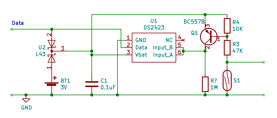
I don’t understand the numbering of the resistors: there only appear to be three, for a start, and I can’t see the screen-printed label for the 1M resistor. U2 is, I believe, a three-pin surface-mount device that contains two Schottky diodes with a common cathode. I’d assume it’s there to protect the two potential power sources from reverse voltages.
It’s also odd that the Dallas rain gauge which may actually be what this design is based on (or vice-versa) doesn’t use the resistor bridge or transistor. Effectively the reed switch is just across Vbat and the two inputs on pins 5 and 6.