
Since it’s relatively easy, I’ll start with the tools required. I think this is pretty much everything I needed for the first build.
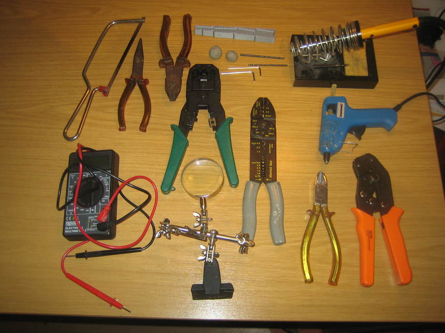
Covering the easy stuff first, obviously there’s the soldering iron. It would be nice to have a proper temperature-controlled iron, but I’ve had some of my tools since I was in my early teens and getting rid of them now is almost unconscionable 🙂 The one in the picture is 18W and has a standard tip about 2mm wide. I did also use a very small tip for the temperature sensor sockets in my first build, but that should be avoidable in the future.
Other easy bits — a hot-melt glue gun which my daughter normally uses for, err, making a sticky mess all over the front of a hot melt glue gun, wire cutters/strippers and a pair of side cutters, a couple of pairs of pliers, junior hacksaw and a multimeter (something else that’s probably twice as old as my children). If all goes well the multimeter really only gets used as a continuity tester or at most a resistance meter.
There’s also a pair of Allen keys to fit the bolts I used — 2mm and 2.5mm in this case, and a pair of drills(2.5mm and 3mm) to drill the holes out for the bolts because it was easier than trying to make them in the design for the case.
In the centre at the bottom is a sort of clamp with a built-in magnifier for holding parts whilst soldering them. These days my eyesight needs a bit of help for the small stuff. It, or a separate magnifying glass, is also handy for checking soldered connections to make sure there aren’t any bridges between joints that shouldn’t have them. Above it is a tool for making up modular sockets. It’s probably one of the more esoteric items, but I have several lying about because I make up all my own network cables. It’s only used for crimping the RJ11 plugs onto the temperature sensors and I think I’m going to use a different sort of socket for this build, so may not be required at all.
Above the crimping tool, a couple of blobs of blutak (showing discolouration due to heavy use, in this case). It can be so handy for holding stuff in place whilst soldering 🙂 And above them, a little 3d-printed tool that really isn’t necessary, but allows the likes of resistor leads to be bent at just the right point to go through the usual 1/10th inch spacing PCB holes. Pliers mostly work just as well.
And finally, bottom right, and the only tool I actually bought specifically for this build because it actually came with some of the components I wanted anyhow, a crimping tool for making up the connectors for pin headers. This actually came in a set with the crimps and plugs — more of that in another post.
I think the only out-of-the-ordinary thing I used that isn’t in the photo is a hot air gun. That’s because in places I used some heatshrink sleeving to make sure joins were insulated.
I did also use a small flat-bladed screwdriver (about 3mm wide). It’s handy for making sure the pins are pressed fully home on the pin header sockets, but otherwise I only used it for adjusting the brightness of the LCD so the text showed up. In fact, for the latter purpose a plastic screwdriver would be a better idea because you do need to be poking it in the general direction of live electrics, so removing the possibility of shorting anything out would be sensible. I feel sure I have one, but I haven’t been able to find it.