
I posted a while back that I’d bought one of these to build with the children as a summer holiday project. As it turned out my son didn’t seem that interested, but my daughter has got involved with the build quite a bit.
Sit down and prepare yourself for a long read 😀
Overall I’d say I was pleased with the quality of the kit. You need to work out which of the aluminium pieces and pressed steel components are which by yourself, but almost everything else is in numbered bags (nearly fifty of them) which are referred to in the instructions. Unfortunately our instructions weren’t entirely consistent with the bag numbering, though it’s not possible to tell if the instructions are wrong or the bags were mislabelled. Perhaps because of this we ended up too short of some screws whilst lots of others were left over. We probably used the wrong length screw in some places without realising it.
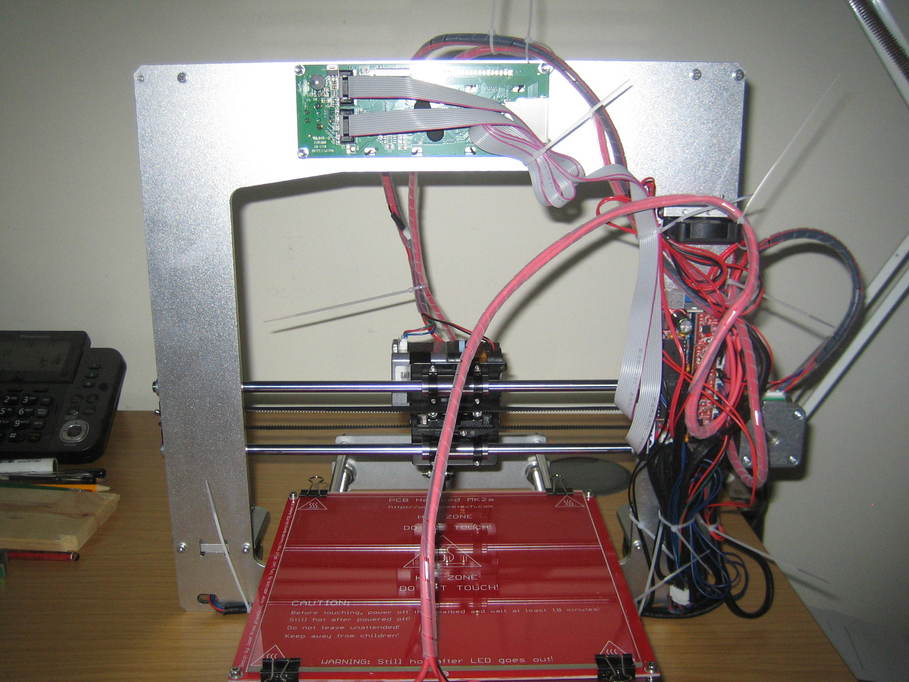
The online videos showing assembly were very helpful, probably necessary in fact, as the instructions don’t give you a whole load of clues about how to assemble some parts. Even so it’s possible to get one or two pieces back-to-front without realising it. My biggest niggle with the instructions was that they leave one or two things completely unclear, partly because they don’t refer to exactly the parts that are shipped (probably an earlier version and they’ve not caught up yet). So for example it wasn’t clear which of the two sockets for the SD card and the LCD display is which and the two ribbon cables supplied to connect them up will fit either. Fortunately it doesn’t appear to do any harm if you get them the wrong way around — you just don’t get anything on the display. The instructions also refer to a version of RepetierHost way behind the current release which can be a bit confusing as some of the setup is not the same any more. It’s hardly the end of the world however. Some help with how to efficiently lay out the cables would be useful, too. There’s an awful lot of loose wire to be tidied away and not a lot of space for it where it won’t interfere with moving parts. There are no instructions about fitting the heatsinks to the stepper motor driver boards, which would probably have been helpful as I didn’t even initially realise that was what they were for.
Some care is also required with the PSU. Mains voltages are exposed to careless fingers. I shall be boxing mine up in the fullness of time.
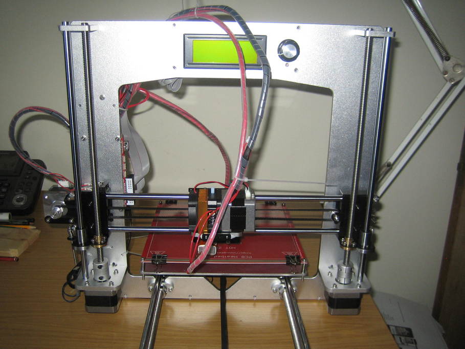
Anyhow, everything assembled, here’s what we ended up with:
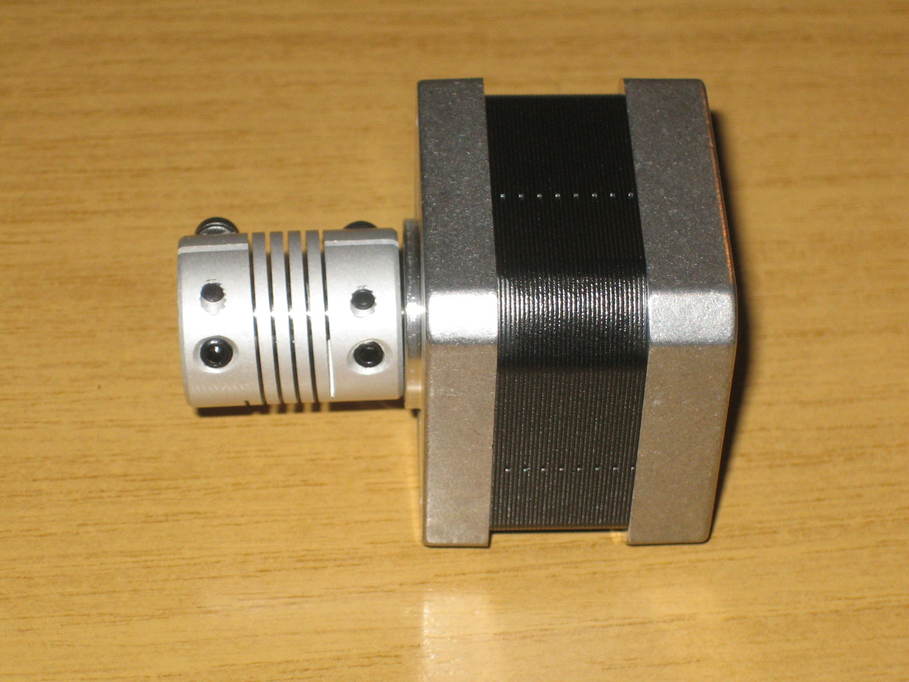
At this point it I started testing. X and Y axis travel looked good, but the Z axis kept sticking (the motors stalled) near the bottom. Rotating the guide bearings 180 degrees helped a little, but the problem was still there. I checked the lead screws and guides were true (they’re pretty good, actually) took the entire thing apart several times to no avail and eventually found that one of the couplings that connects the left-hand lead screw to the motor was faulty. The bores (one 8mm for the lead screw and one 5mm for the motor shaft) were not concentric, resulting in the lead screw oscillating and eventually binding near the bottom where there wasn’t enough play in the other components to cope. Replacing the connector resolved the problem completely and my Z axis worked correctly from then on. It’s possible to see in this image of the original connector that it isn’t square on to the motor (there’s a larger gap between the two at the top than the bottom) despite being correctly fitted.
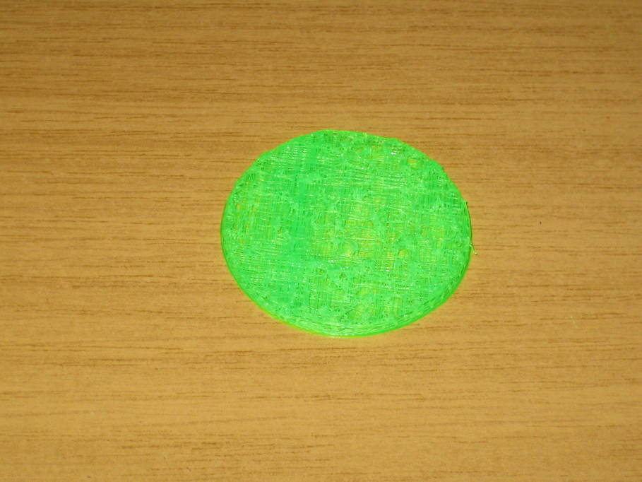
Bed levelling went fine and I downloaded the proposed test piece (a disc about 50mm diameter and 3mm high). Printing was a total disaster! It didn’t matter how much I messed about with print speed, feed rates, extruder temperature or anything like that, I just couldn’t get a usable print. My best one ended up looking like this:
Eventually I realised that the filament wasn’t feeding through the extruder correctly. Though it comes as one unit in the kit I had to take it apart and see what was going on. This is what it looks like with the fan and heatsink removed.
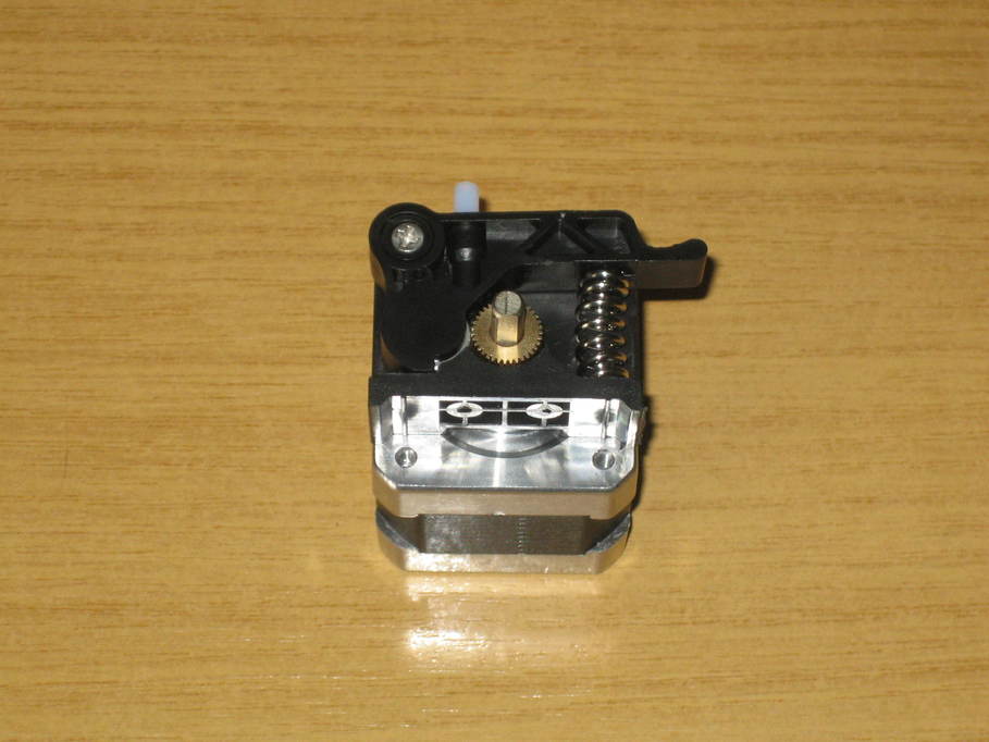
The filament is supposed to feed down between the toothed wheel and an idler pulley, the teeth gripping the filament and pushing it through into the nozzle. The teeth on this one clearly weren’t gripping the filament and it was possible to pull and push the filament past without it moving.
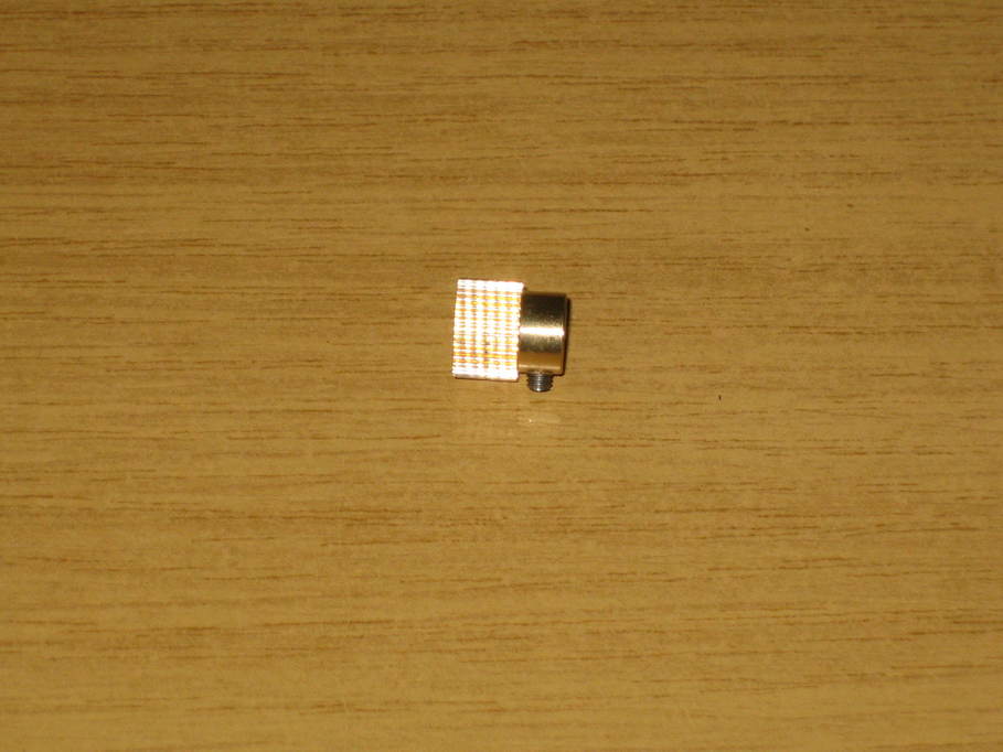
I ended up replacing that wheel with a stainless steel one and putting a screw upside down inside the tensioning spring to preload it a little to get a reliable feed rate on the filament as measured on my desk.
Reassembled however, I was back to the start! I still couldn’t get a decent print. After lots more times around the disassembly/reassembly loop I decided to check the voltages on the stepper driver to see if the motor perhaps just wasn’t getting enough power. These allegedly ship from the factory set at 0.6V. Mine measured at 0.05V. A little adjustment raised it by…. nothing at all. More and more still gave me nothing until suddenly it jumped from 0.05V to 4.5V. Looks like the pot on the stepper driver is dead. I ordered a few more as spares and unbelievably the first one I tried out was also dead. The second one was perfect however. With everything reassembled I managed two lovely disc prints straight off the bat, so the problem was clearly two-fold. First the extruder motor wasn’t gripping the filament well enough to push it into the hot end and second it wasn’t able to push it firmly enough to keep the hot end supplied with sufficient material to create the print.
I think that’s quite enough for one post, so I’ll write up my first “proper” print in a separate post.